Main Controller and Power Board Wiring Diagrams
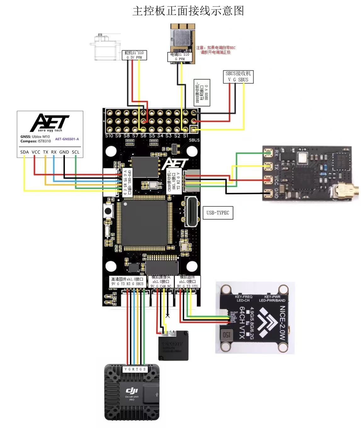
Flight controller tutorial supplement: T/R port identification, receiver wiring, and serial-port parameter configuration
1. Basic Label Definitions
On the PCB silkscreen, T = Transmit (transmit pin, data output), and R = Receive (receive pin, data input).
Each Tx/Rx pair corresponds to one hardware serial port:
Example: T2 and R2 → hardware serial port 2 (UART2)
T2: serial port 2 transmit pin
R2: serial port 2 receive pin
2. Receiver Wiring Logic (Important)
Serial receiver wiring rule (this flight controller supports only SBUS and ELRS):
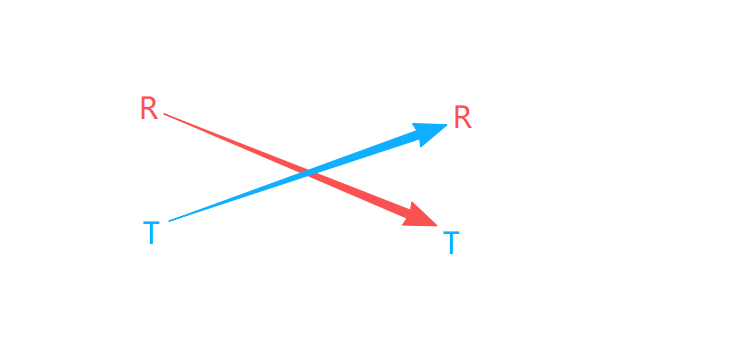
Receiver output signal → flight controller receive pin; use cross-wiring.
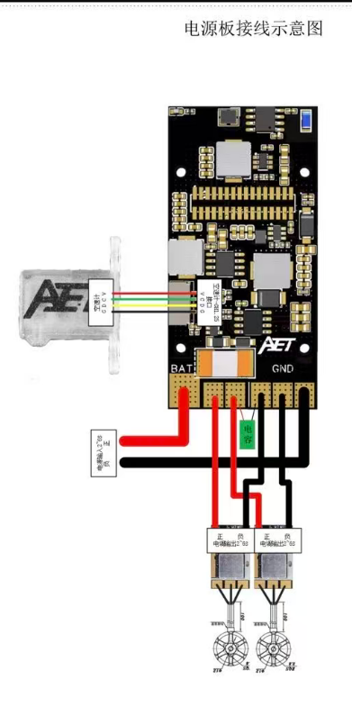
The power board provides only two soldered output positions. To connect three or more leads, use a power distribution board or a one-to-two splitter.
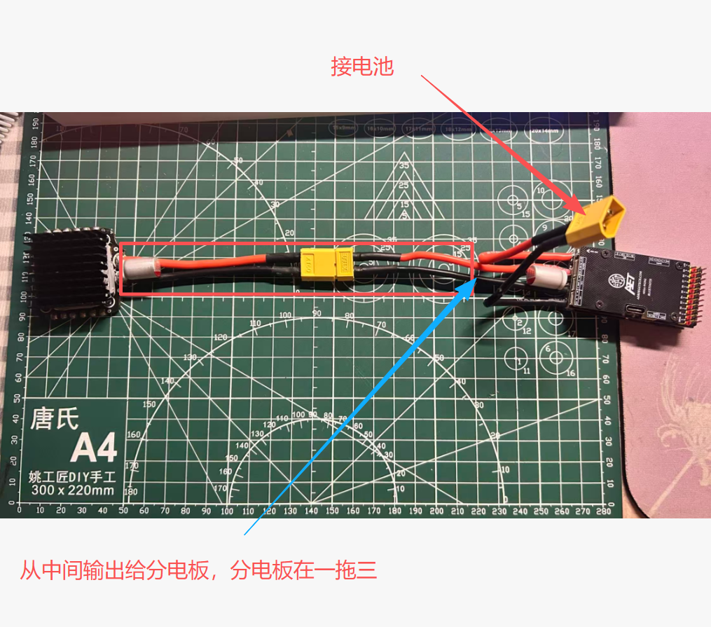
Important Notes
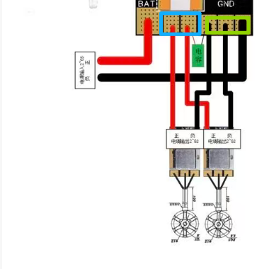
The blue and green pads on the left may be bridged. Never connect the positive and negative terminals; doing so will create a direct short circuit and damage the flight controller power board and main controller.
The circuit on the right contains a series current-sense resistor. Bridging it will bypass the sense resistor, disabling current measurement, endurance estimation, and protection functions.
If the pads are accidentally bridged, remove the solder with desoldering braid and restore isolation between the pads.