Industrial GPS-CAN Configuration Guide
Step 1: Physical Connections Ensure that the CAN GPS and CAN compass modules are correctly connected to the flight controller's CAN bus.
Flight controller CAN interface: the pins are normally labeled CAN_H and CAN_L. Wiring:
Connect CAN_H from all CAN devices (GPS and compass) in parallel to CAN_H on the flight controller.
Connect CAN_L from all CAN devices in parallel to CAN_L on the flight controller.
Connect power (5V or 9V) and ground (GND) to all devices.
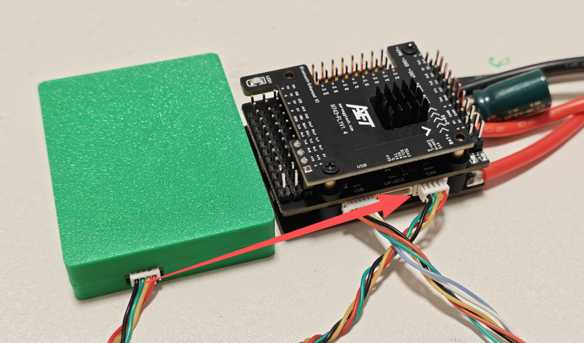
Key point: CAN is a parallel bus; all devices share the same signal pair.
Step 2: Enable and Configure the CAN Bus The flight controller must recognize the CAN bus before any CAN devices can be configured.
Connect the flight controller to the computer via USB, open Mission Planner, and connect to the flight controller.
Go to CONFIG/TUNING -> Full Parameter List.
Locate and change the following parameters:
CAN_P1_DRIVER = 1
Purpose: enables the CAN1 port driver on the flight controller.
CAN_D1_PROTOCOL = 1
Purpose: sets the communication protocol for this CAN bus. A value of 1 selects DroneCAN, the CAN protocol most commonly used by ArduPilot.
After making the changes, click Write Params, then completely power-cycle the flight controller. This step is essential because the CAN bus configuration takes effect only after a restart.
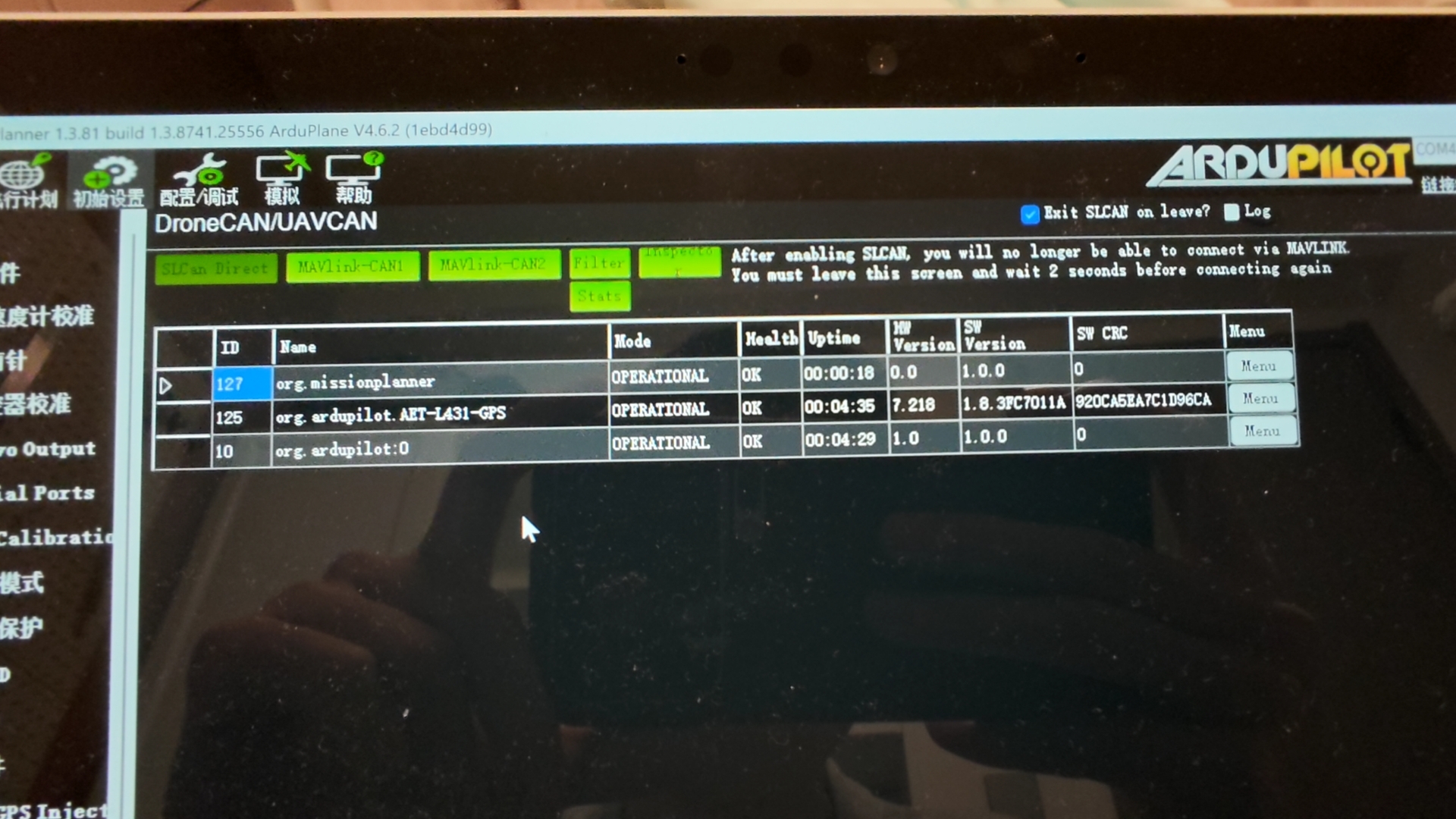
AET-L431-GPS can be detected under DroneCAN:
Step 3: Configure CAN GPS Parameters
After restarting and reconnecting the flight controller, configure the GPS parameters.
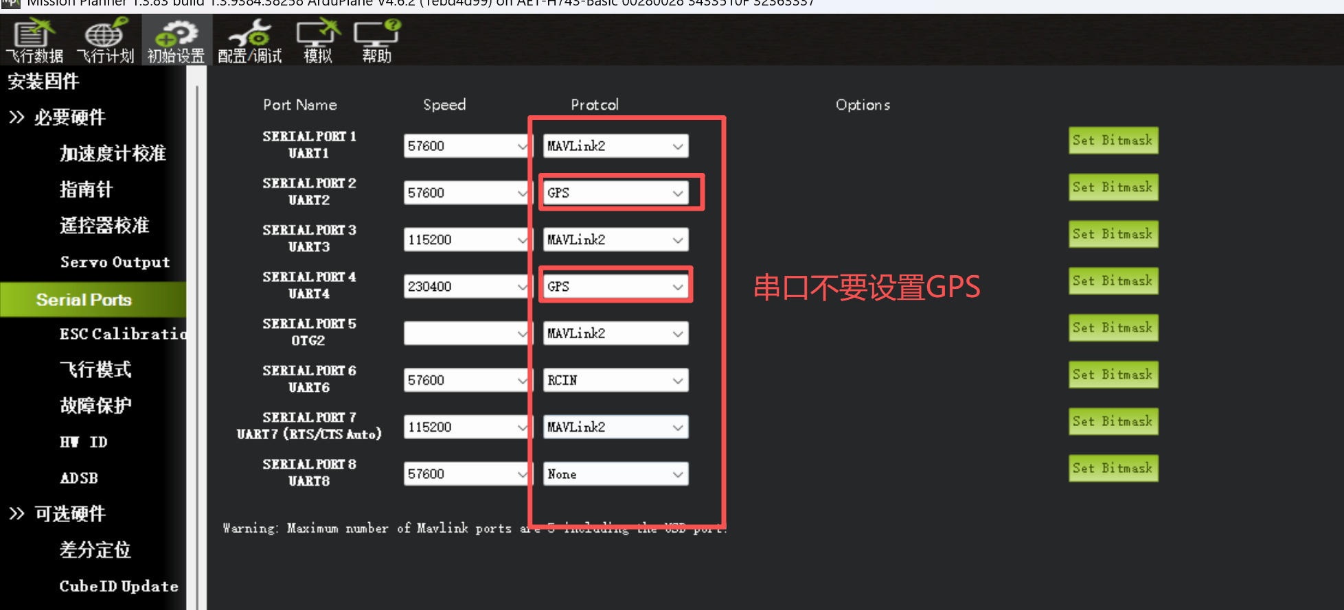
Continue configuring the following values in Full Parameter List:
GPS1_TYPE = 9
Purpose: sets the primary GPS (GPS1) type to DroneCAN GPS. The flight controller automatically scans the CAN bus for GPS devices.
GPS_CAN_OVRIDE = 0
Purpose: 0 enables automatic detection. If multiple CAN GPS devices are present on the bus, specify the unique Node ID here. Normally, leave this parameter at 0 initially.
Step 4: Configure CAN Compass Parameters
Next, configure the flight controller to use the compass on the CAN bus.
In Full Parameter List, locate the parameters for compass 1. The flight controller's onboard compass is normally assigned to COMPASS_DEV_ID1.
Add or enable the CAN compass. The second compass instance (COMPASS_DEV_ID2) is normally used:
COMPASS_USE2 = 1
Purpose: enables the second compass.
COMPASS_DEV_ID2 = 1
Purpose: sets the device type for the second compass. A value of 1 selects a DroneCAN compass.
COMPASS_CAN_OVRIDE2 = 0
Purpose: as above, 0 automatically detects the CAN compass Node ID. Enter the applicable ID if manual selection is required.
Note: To disable the flight controller's onboard compass, which may be more affected by onboard electromagnetic interference, set COMPASS_USE1 = 0.
Step 5: Inspect, Calibrate, and Verify After configuring all parameters, click Write Params and restart the flight controller again.
Check device status:
GPS: On the Flight Data screen, verify that the GPS status icon at the top changes from red to yellow and then green. Open the GPS page to check satellite count, fix type, and HDOP. Compass: Go to INITIAL SETUP -> Compass. Multiple compasses, such as Compass1 and Compass2, should be listed. Ensure that the intended CAN compass is enabled with Use. Its health status should indicate Healthy.
Calibrate the compass:
On the Compass page, click Calibrate. Follow the prompts and slowly rotate the aircraft through all six orientations until the progress bar completes.
Set compass priority:
On the Compass page, drag the compasses to change their priority. Move the external CAN compass, normally installed on a wingtip or vertical stabilizer away from motors and power wiring, to the highest priority so the flight controller uses the least disturbed magnetometer data.
Common Problems and Troubleshooting
GPS or compass is not displayed or is unhealthy
Check the wiring: verify that CAN_H and CAN_L are not reversed or shorted and that power is normal. Confirm that the parameters took effect: ensure that Write Params -> complete power cycle was performed. Check the Node ID: some CAN devices use a fixed Node ID. If automatic detection fails, consult the device manual and enter the ID manually in GPS_CAN_OVRIDE or COMPASS_CAN_OVRIDE2.
Compass calibration fails or interference is excessive
Installation location: install the CAN compass module away from motors, ESCs, power cables, and servo leads. Calibration environment: keep away from metal objects, mobile phones, computers, and other strong magnetic-field sources during compass calibration.
Unable to connect to the flight controller or write parameters
Ensure that the flight controller is in normal operating mode, not DFU flashing mode.
Summary: enable the CAN bus -> set the device type to DroneCAN -> perform a complete power cycle -> calibrate and verify. Following this process allows the CAN GPS and compass to operate correctly.