Fixed-Wing Aircraft
U7 Flight Controller AGC Configuration and Tuning Guide
1. Confirm the Aircraft Type
2. Flash the Firmware
3. Peripheral Wiring and Configuration
4. Basic Flight Controller Configuration and Tuning
5. Flight Mode Configuration
6. Detailed Parameters for Each Flight Mode
7. Failsafe
1. Confirm the Aircraft Type
The U7 flight controller supports multirotors (arducopter), traditional helicopters (traditional copter), fixed-wing aircraft (arduplane), VTOL aircraft including Y3 and 4+1 configurations, ground vehicles (ardurover), and boats (ardurover). Use the firmware corresponding to the aircraft or vehicle type as follows:
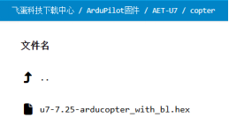
Multirotor:
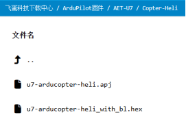
Traditional helicopter: Files ending in apj are flashed with MP; with_bl files are flashed through AGC. This guide uses AGC.
Fixed-wing and VTOL aircraft, including Y3, X4, and 4+1:
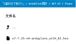
Important: Select firmware strictly according to the file name. Flash hex firmware in DFU mode using STM32CubeProgrammer, MissionPlanner 1.3.82 or later, or INAV Configurator. Flash apj firmware with MissionPlanner only after confirming that the board uses an AET bootloader, for example after previously flashing AET hex firmware.
2. Flash the Firmware
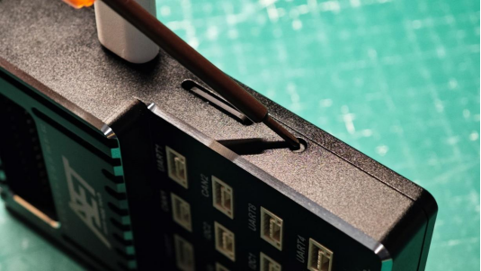
1. Hold the flight controller Boot button and connect the flight controller to the computer with a USB-TYPEC data cable.
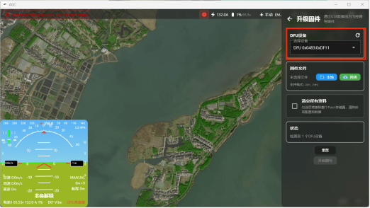
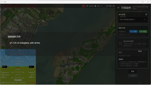
2. Open the gear menu in the upper-right corner, select the firmware upgrade item at the bottom, and click Refresh under DFU Device. The flight controller is selected automatically.
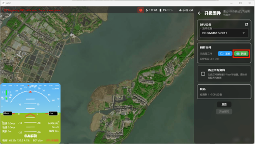
3. Under Firmware File, select the green “Network” option.
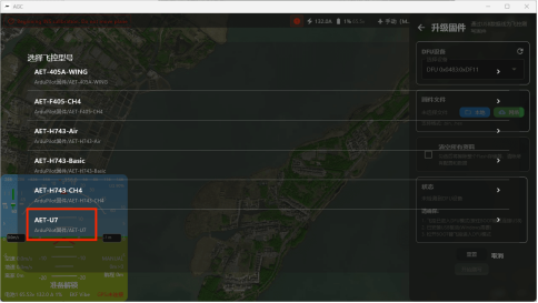
4. Select “AET-U7” at the bottom.
5. Select the firmware to flash. This example uses fixed-wing firmware (Arduplane).
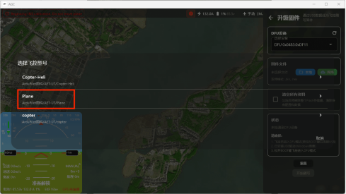
6. Click the firmware file.
7. Enable “Erase All Data” even though it is not selected in the illustration, then click the blue Start Flashing button.
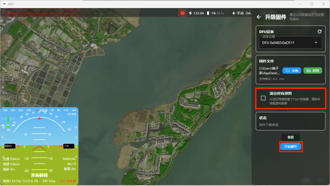
Important: Do not disconnect the flight controller from the computer while firmware is being flashed.
3. Peripheral Wiring and Configuration
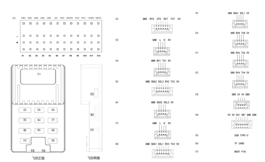
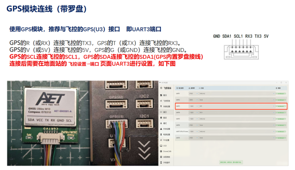
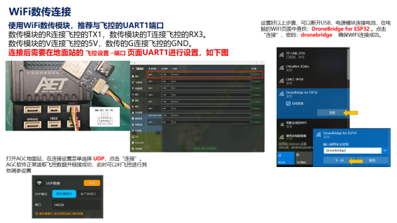
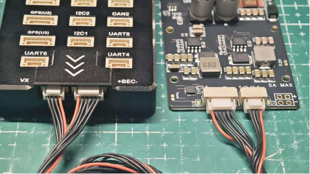
Use this diagram to verify the wire order between each peripheral and the flight controller.
1. Receiver
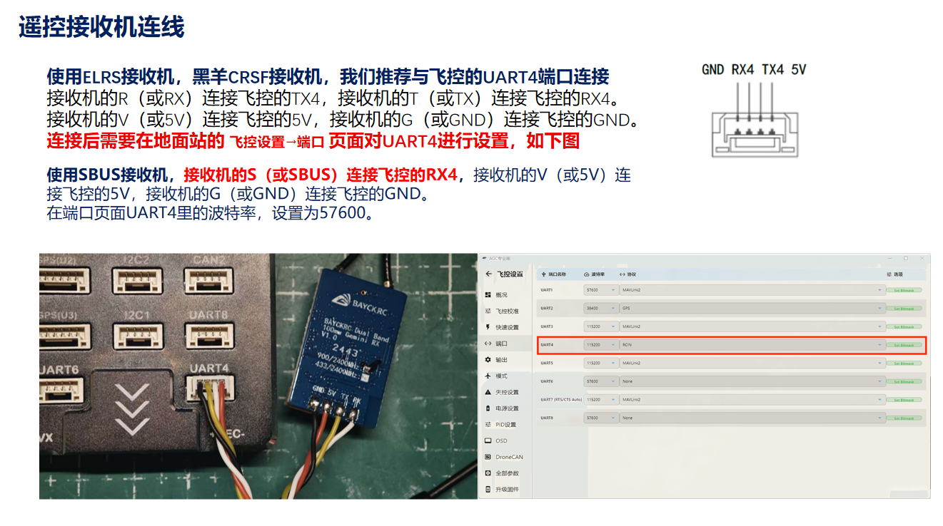
2. UART-Protocol GPS
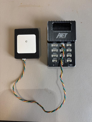
3. CAN-Protocol GPS
Use the cable supplied with the CAN-protocol GPS to connect the GPS to the CAN1 port.
4. Wi-Fi Telemetry Configuration
5. PMU Connection
6. ESC Connection
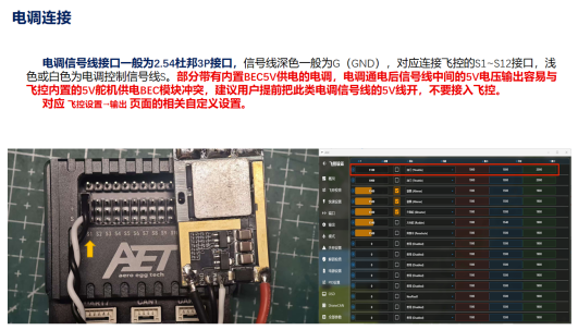
The flight controller Timer groups are 12, 3456, and 78910. A single group cannot contain both servos and ESCs (motors); choose only one output type per group.
Dshot is recommended. The flight controller uses PWM output by default. To change PWM to DSHOT:
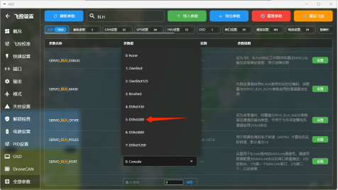
On Flight Controller Settings > Full Parameters, search for BLH in the search box at the top.
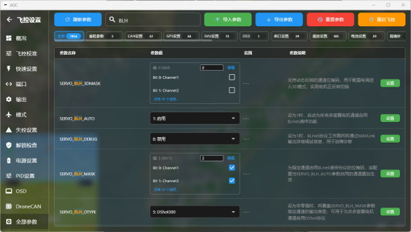
Set the displayed parameters as follows:
SERVO_BLH_AUTO = 1
Open BLH_MASK.
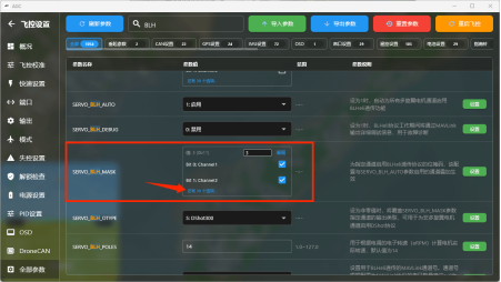
Select the Channel number matching the S output where the ESC is connected, as labeled on the flight controller.
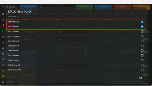
Set BLH_OTYPE to a protocol supported by the ESC. Dshot300 is generally recommended.
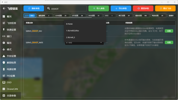
Search for SERVO_DSHOT_ESC and select the firmware type used by the ESC.
After completing all changes, fully power-cycle the flight controller to apply the settings.
4. Basic Flight Controller Configuration and Tuning
1. On Flight Controller Settings > Flight Controller Calibration, select the first item, Accelerometer Calibration. Select six-side calibration and click Start Calibration.
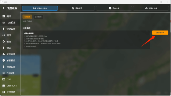
Click Confirm in the dialog.
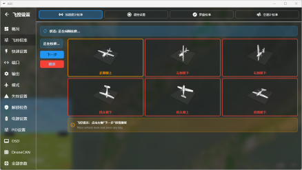
Complete the six-side calibration according to the on-screen illustrations. After positioning the aircraft on each side, click Next.
A calibration-success message appears when the procedure is complete.
Level calibration: After the aircraft is fully assembled, place it on a level surface and run the calibration once.
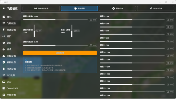
2. Radio Transmitter Calibration (begin after configuring the receiver)
Click Start Calibration and follow the prompts.
3. Servo Calibration
The servo wiring should have been installed together with the ESC wiring. Configure the servos next. The following example uses a twin-engine fixed-wing layout.
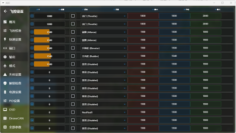
As shown, connect the ESCs to S1 and S2, the ailerons to S3 and S4, the elevator to S5, and the rudder to S6.
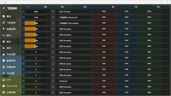
A single-engine rear-pusher flying wing is shown below:
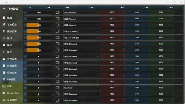
A rear-pusher V-tail fixed-wing aircraft is shown below:
After configuring the servos, switch the flight mode to FBWA. Without moving the radio transmitter sticks, lift and tilt the aircraft in each direction and observe the control-surface response:
When the nose pitches up, the elevator deflects down;
When the nose pitches down, the elevator deflects up;
When the aircraft rolls left, the right aileron moves up, the left aileron moves down, and the rudder deflects right;
When the aircraft rolls right, the left aileron moves up, the right aileron moves down, and the rudder deflects left.
If any response differs, enable Reverse for the corresponding output.
Next, verify Manual mode: pulling the pitch stick must move the elevator up; pushing it must move the elevator down. A left-roll command must move the left aileron up and right aileron down; a right-roll command must move the right aileron up and left aileron down. A left-yaw command must deflect the rudder left; a right-yaw command must deflect it right. If any response is reversed, reverse that channel on the radio transmitter.
5. Flight Mode Configuration
On Flight Controller Settings > Modes, configure the required flight modes in the Flight Mode Settings section on the left. To change the default flight-mode switch channel, select the desired channel in Flight Mode Channel at the top. Channels assigned to other channel-switch options on the right must not match the flight-mode channel.
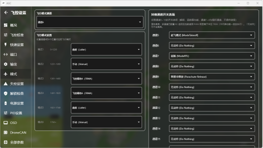
MANUAL Manual mode. The flight controller does not stabilize or control the aircraft.
CIRCLE Circle mode.
STABILIZE Basic stabilization mode. The controller returns the aircraft toward level attitude while allowing attitude control from the radio transmitter. Use this mode if FBWA response feels too slow.
FBWA Stabilized mode. The aircraft follows configured roll and pitch limits and maintains attitude effectively; altitude is controlled with throttle. Recommended for beginners.
FBWB Stabilized altitude-hold mode. Adds effective altitude holding to FBWA behavior.
CRUISE Cruise mode. Maintains altitude and heading; strongly recommended for long-range flight.
ACRO Attitude-lock mode, similar to manual mode on an FPV racing drone. Releasing the sticks locks the current attitude.
AUTOTUNE Automatic configuration and tuning mode.
AUTO Automatic waypoint mode.
LOITER Loiter mode. Circles around the current position using the configured altitude and radius.
RTL Return-to-launch mode. Returns in a straight line to the home position, then circles using the configured altitude and radius.
TAKEOFF Assisted hand-launch mode.
6. Detailed Parameters
1. FBWA Parameter Fine-Tuning
ROLL_LIMIT_DEG 60 Maximum roll angle in FBWA mode. Default: 45.
A value of 60 is recommended to reduce the turning radius in FBWA mode.
PTCH_LIM_MAX_DEG 35 Maximum pitch angle in FBWA mode.
Default: 20. A value of 35 is recommended to increase the permitted climb angle and improve climb rate in FBWA mode.
2. RTL Configuration
RTL_ALTITUDE 100 m Default: 100m. Circling altitude after RTL reaches the launch point. If set to -1, the aircraft returns at its current altitude and circles above the launch point.
WP_LOITER_RAD 80 Loiter radius. Default: 60m.
For example, an 80 m radius with a 40-second orbit generally provides efficient throttle and airspeed during circling.
3. RSSI Configuration
SIYI and TBS CRSF receivers use a PWM channel to represent the RSSI signal. SIYI uses CH16, TBS CRSF uses CH12, and ELRS uses CH15. Set the following parameters under RSSI:
RSSI_TYPE 2 (use one PWM channel as the RSSI signal input
ELRS receivers primarily use LQ to report link quality, so select 3 for this parameter)
Write the parameter, disconnect and reconnect the flight controller, then search for RSSI_CHANNEL.
For a SIYI receiver, set RSSI_CHANNEL to 16.
For a CRSF receiver, set RSSI_CHANNEL to 12.
For an ELRS receiver, set RSSI_CHANNEL to 15.
During radio calibration, the radio signal remains at full strength, causing both the maximum and minimum values for the RSSI channel to remain at 2000: channel 16 for SIYI, channel 12 for TBS CRSF, or channel 15 for ELRS. Adjust the minimum and maximum values for that channel to ensure the RSSI data range is correct.
The following example configures ELRS RSSI on channel 15. In the Full Parameter List, search for RC15. For SIYI, search for RC16; for TBS CRSF, search for RC12.
RC15_MAX 2000
RC15_MIN 1000
The RSSI value for the corresponding channel will then display correctly during flight.
7. Failsafe
Ardupilot failsafe logic triggers when the flight controller detects a receiver throttle output below 1000. Users familiar with inav or bf will recognize that when the radio transmitter is not connected to the receiver, or the flight controller does not detect the receiver, the throttle value remains fixed at 885. Some firmware versions use conservative failsafe behavior, so perform a failsafe check.
FS_SHORT_TIMEOUT 1.5 (after receiver throttle output is lost for 1.5 seconds, the flight controller performs the first-stage failsafe action)
FS_SHORT_ACTN 1 (first-stage failsafe action: enter CIRCLE and wait. Default: 0, “No action”)
FS_LONG_TIMEOUT 5 (if no throttle output signal is received for 5 seconds after the first-stage failsafe begins, the flight controller performs the second-stage failsafe action)
FS_LONG_ACTH 1 (second-stage failsafe action: execute RTH. Default: 0, “Continue current action”)
Ardupilot firmware uses a default 100 m circling altitude at the return point. Adjust it for local terrain and operating conditions. RTL flies a straight line toward the launch point while descending during the return.
If the aircraft is below the configured altitude, it climbs rapidly to that altitude before continuing RTL.
After configuring these parameters, test the failsafe while the aircraft is disarmed. Remove the propellers, then turn off the radio transmitter. A “Fail safe” message should appear immediately.