Multirotor
U7 Flight Controller AGC Configuration and Tuning Guide
I. Identify the Airframe Type
II. Flash the Firmware
III. Peripheral Wiring and Configuration
IV. Basic Flight Controller Configuration and Tuning
V. Flight Mode Setup
VI. Detailed Parameters for Each Flight Mode
VII. Failsafe
I. Identify the Airframe Type
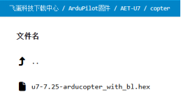
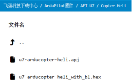
The U7 flight controller supports multirotors (arducopter), traditional helicopters (traditional copter), fixed-wing aircraft (arduplane), VTOL aircraft (including Y3 and 4+1 configurations), ground vehicles (ardurover), and boats (ardurover). Use the firmware corresponding to the required airframe type, as shown below.
Multirotor:
Traditional helicopter: Files ending in apj are flashed with MP, while with_bl files are flashed through AGC. This guide uses AGC.
Fixed-wing and VTOL aircraft (including Y3, X4, and 4+1):
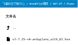
Important: Select firmware strictly by its file name. Flash hex firmware in DFU mode using a tool such as STM32CubeProgrammer, MissionPlanner 1.3.82 or later, or INAV Configurator. Flash apj firmware with MissionPlanner only after confirming that the board uses the AET bootloader, for example after previously flashing an AET hex firmware image.
II. Flash the Firmware
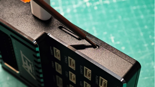
1. Hold down the Boot button on the flight controller and connect it to the computer with a USB-TYPEC data cable.
2. Click the gear icon in the upper-right corner, open the Firmware Upgrade option at the bottom, and click Refresh under DFU Device. The flight controller should be selected automatically.
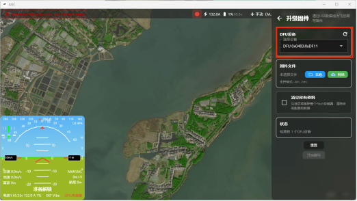
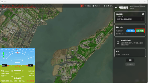
3. Select the green Network option for the firmware file.
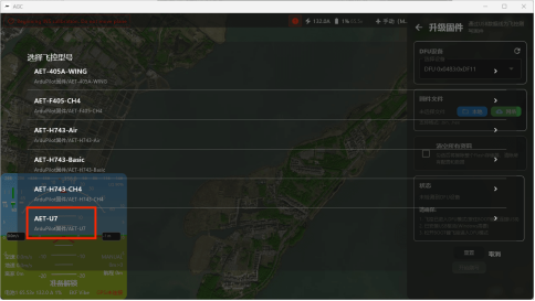
4. Select “AET-U7” at the bottom of the list.
5. Select the required firmware. This example uses the multirotor firmware.
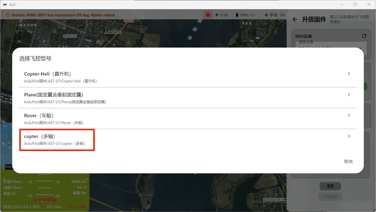
6. Click the firmware file.
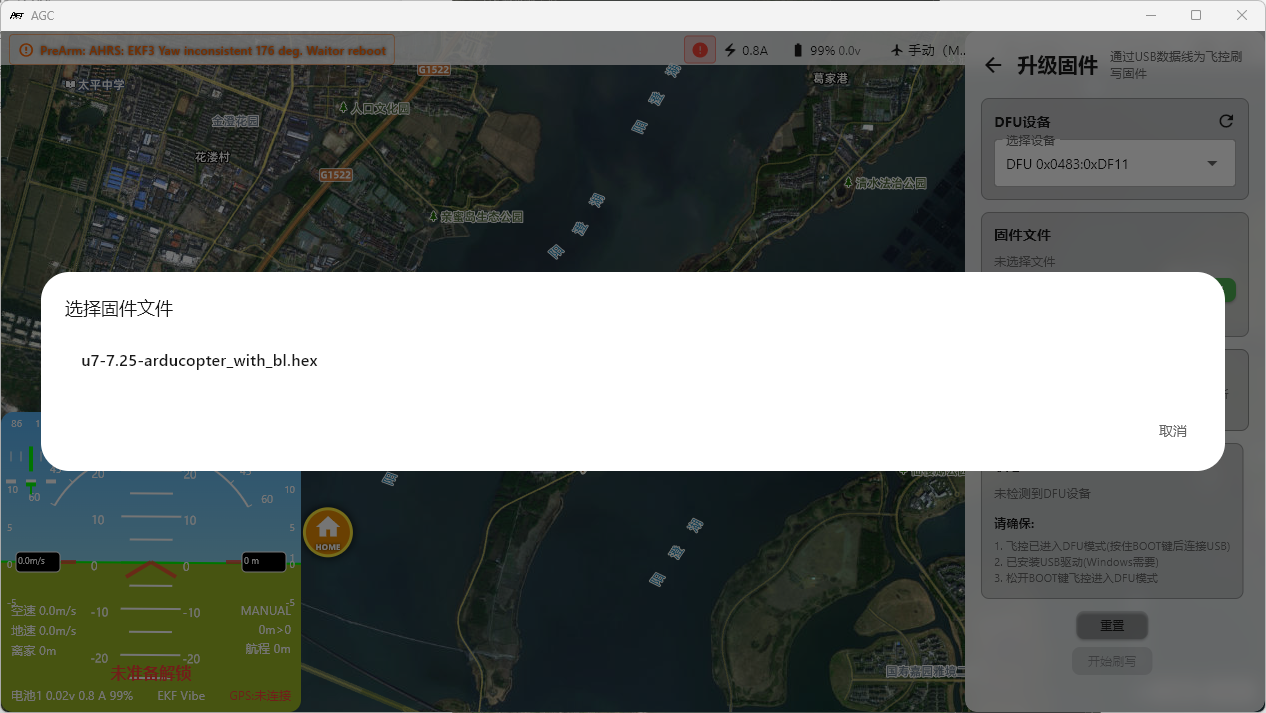
7. Enable Erase All Data. Although it is not selected in the screenshot, it must be enabled. Then click the blue Start Flashing button.
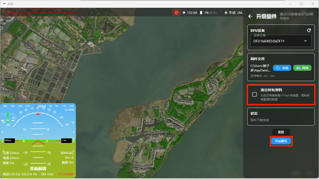
Important: Do not disconnect the flight controller from the computer while firmware flashing is in progress.
III. Peripheral Wiring and Configuration
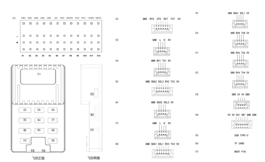
Use this diagram to verify the pin order between each peripheral and the flight controller.
1. Receiver
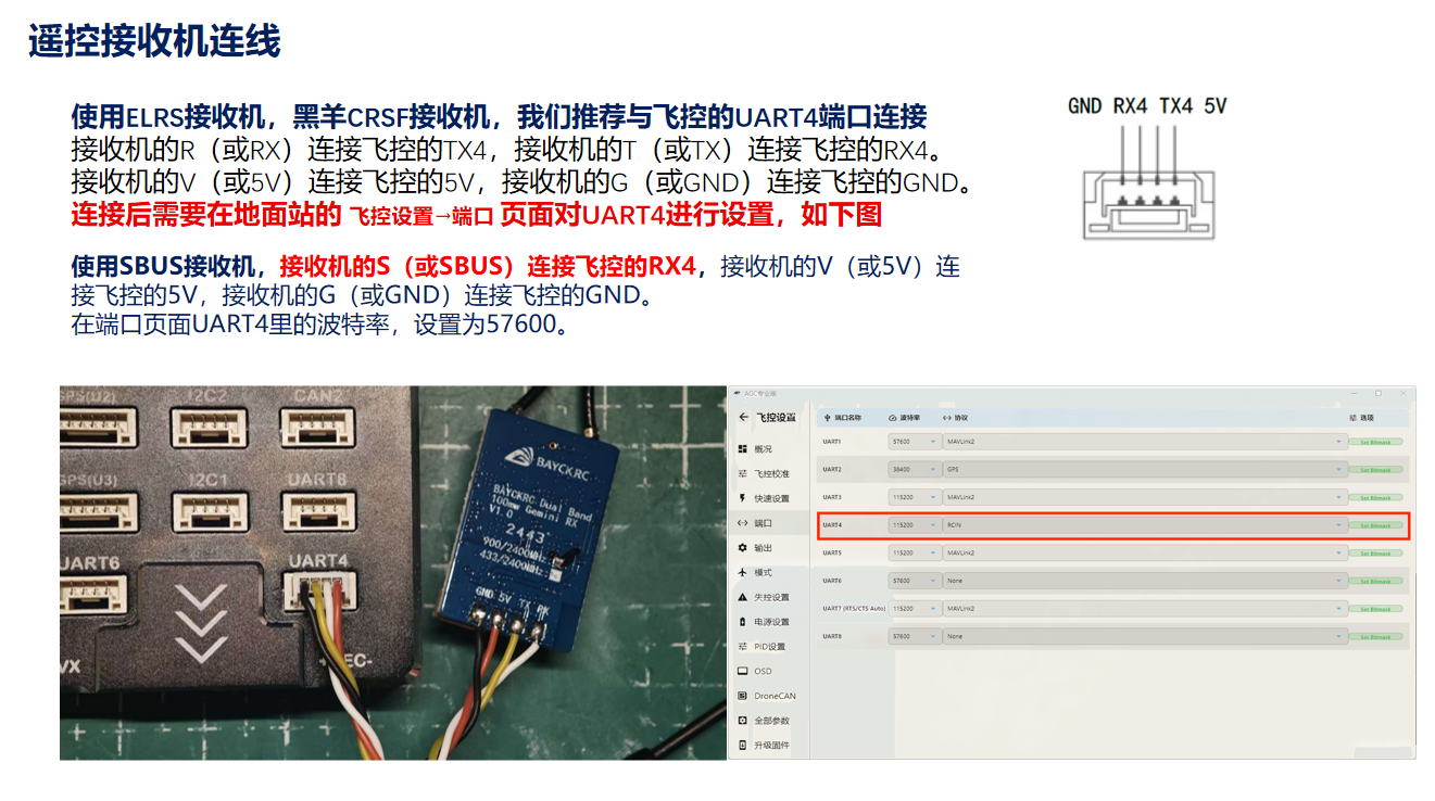
2. UART-Protocol GPS
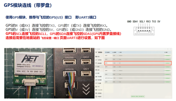
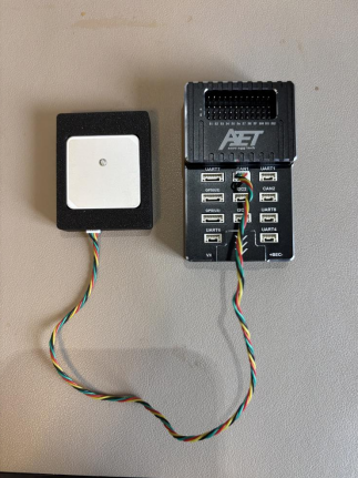
3. CAN-Protocol GPS
Use the cable supplied with the CAN-protocol GPS to connect the GPS to the CAN1 port.
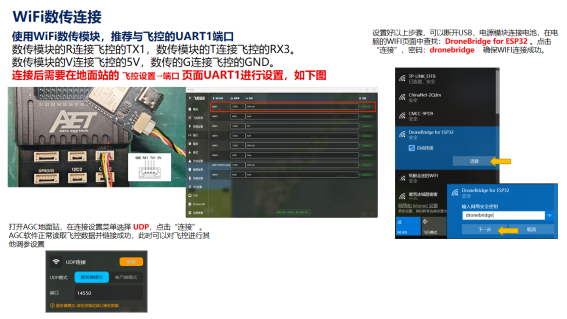
4. Wi-Fi Telemetry Link Setup
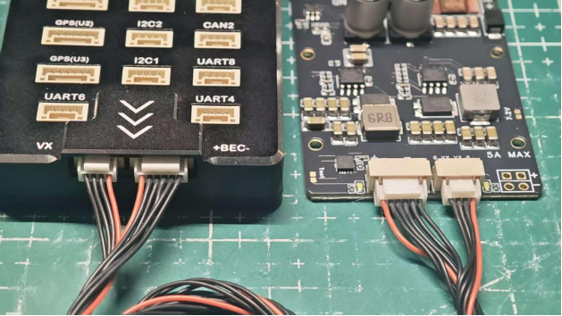
5. PMU Connection
6. ESC Connection
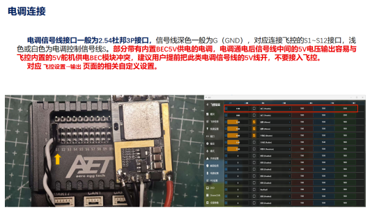
Important: Connect the front-right motor to S1, rear-left motor to S2, front-left motor to S3, and rear-right motor to S4.
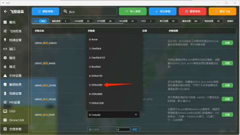
Dshot is recommended. The flight controller uses PWM output by default. Use the following procedure to change PWM to DSHOT:
On Flight Controller Settings → All Parameters, search for BLH in the search field at the top.
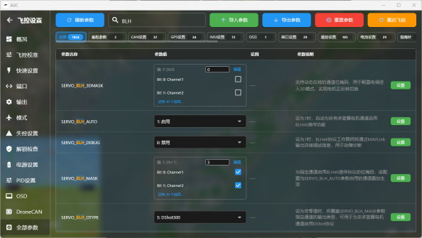
In the displayed parameters:
SERVO_BLH_AUTO = 1
Open BLH_MASK.
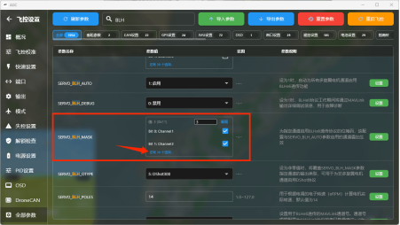
Select the Channel number that corresponds to the S output used by the ESC, as labeled on the flight controller.
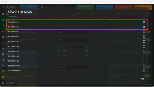
BLH_OTYPE: Set this to a protocol supported by the ESC. Dshot300 is generally recommended.
Search for SERVO_DSHOT_ESC in the field at the top and select the firmware used by the ESC.
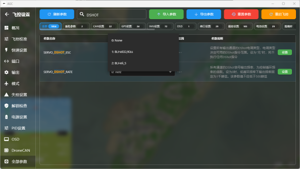
After completing all changes, fully power-cycle the flight controller to apply the settings.
IV. Basic Flight Controller Configuration and Tuning
1. On Flight Controller Settings → Flight Controller Calibration, open the first item, Accelerometer Calibration, select six-side calibration, and click Start Calibration.
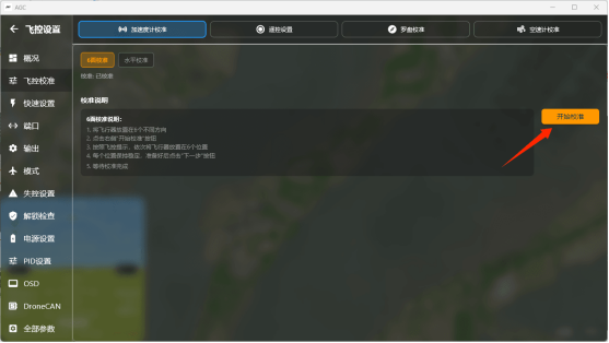
Click OK in the dialog.
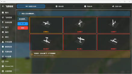
Follow the on-screen illustrations to complete all six orientations. After positioning the flight controller on each side, click Next.
A calibration-success message appears when the procedure is complete.
Level calibration: After the aircraft is fully assembled, place it on a level surface and run this calibration once.
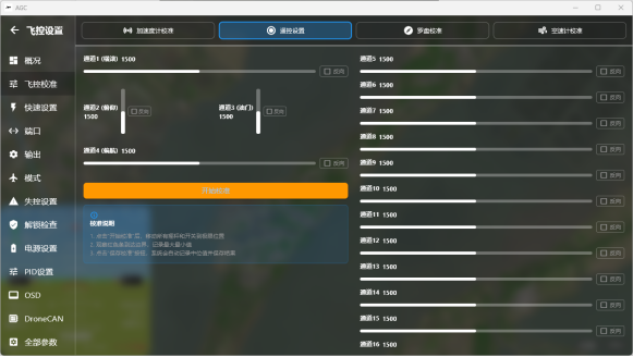
2. Radio Transmitter Calibration (perform after configuring the receiver)
Click Start Calibration and follow the on-screen instructions.
3. Frame Setup
Open Flight Controller Settings → Quick Setup and select the frame type. The default is X4 and normally does not need to be changed.
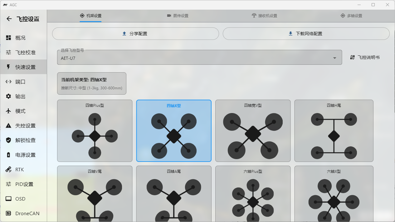
Click the frame icon to select the aircraft size and apply a quick setup.
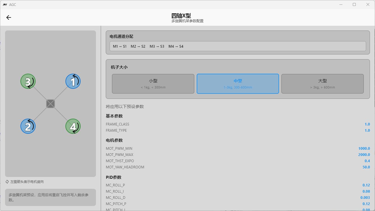
Move the control to the lowest position and click Apply to complete the quick setup.
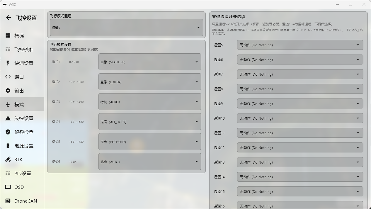
V. Flight Mode Setup
Under Flight Mode Setup on the left side of Flight Controller Settings → Modes, configure the flight modes as required. To change the default mode-selection channel, select the desired channel in Flight Mode Channel at the top. Channels assigned to other switches on the right must not be the same as the flight-mode channel.
VI. Detailed Parameters
1. RTL Mode Setup
RTL_ALTITUDE 100 m Default: 100m. Sets the loiter altitude after RTL reaches the takeoff point. When set to -1, the aircraft returns at its current altitude and loiters above the takeoff point.
2. RSSI Setup
SIYI and TBS CRSF receivers use a PWM channel to represent RSSI. SIYI uses CH16, TBS CRSF uses CH12, and ELRS uses CH15. Configure the following parameter under RSSI:
RSSI_TYPE 2 (use a PWM channel as the RSSI signal input
ELRS receivers primarily use LQ to report signal quality, so select 3 for this parameter.)
Write the parameter, disconnect and reconnect the flight controller, then search for “RSSI_CHANNEL”.
For a SIYI receiver, set RSSI_CHANNEL 16.
For a CRSF receiver, set RSSI_CHANNEL 12.
For an ELRS receiver, set RSSI_CHANNEL 15.
During radio transmitter calibration, the radio signal remains at full strength. As a result, both the maximum and minimum values may remain at 2000 for SIYI channel 16, TBS CRSF channel 12, or ELRS channel 15. Adjust the minimum and maximum values for the relevant channel to ensure that the RSSI indication uses the correct range.
The following example configures ELRS RSSI on channel 15. In All Parameters, search for RC15. For a SIYI receiver, search for RC16; for a TBS receiver, search for RC12.
RC15_MAX 2000
RC15_MIN 1000
The RSSI value for the corresponding channel will then display correctly during flight.
VII. Failsafe
Ardupilot triggers failsafe actions when the flight controller detects a receiver throttle output below 1000. Users familiar with inav or bf will recognize that when the radio transmitter is not linked to the receiver, or the flight controller does not detect the receiver, the throttle value is fixed at 885. Failsafe behavior is conservative in some firmware versions, so perform a failsafe test before flight.
FS_SHORT_TIMEOUT 1.5 (after receiver throttle output is lost for 1.5 seconds, the flight controller performs the first-stage failsafe action)
FS_SHORT_ACTN 1 (first-stage failsafe action: enter CIRCLE and loiter. Default 0 means “no action”)
FS_LONG_TIMEOUT 5 (if no throttle output is received within 5 seconds after the first-stage action begins, the flight controller performs the second-stage failsafe action)
FS_LONG_ACTH 1 (second-stage failsafe action: execute RTH. Default 0 means “continue the current action”)
The default Ardupilot loiter altitude above the home point is 100 meters. Adjust this value for the terrain and operating environment. During RTL, the aircraft flies a straight line toward the takeoff point while descending.
If the current altitude is below the configured RTL altitude, the aircraft automatically climbs rapidly to that altitude before returning.
After configuring these parameters, remove the propellers, keep the aircraft disarmed, and turn off the radio transmitter to test the failsafe. A “Fail safe” message should appear immediately when the transmitter is switched off.