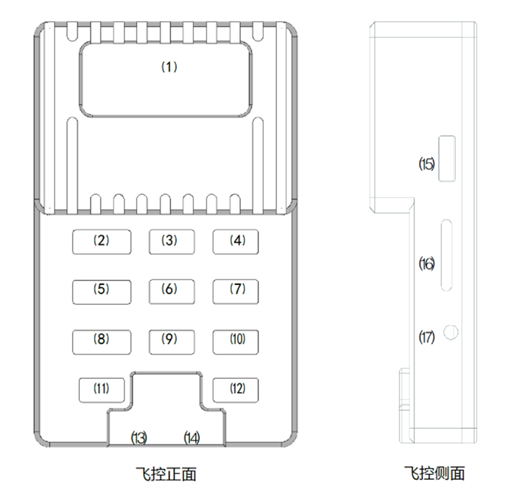
Chapter 2: Flight Controller Interface Diagram (Wiring Instructions)
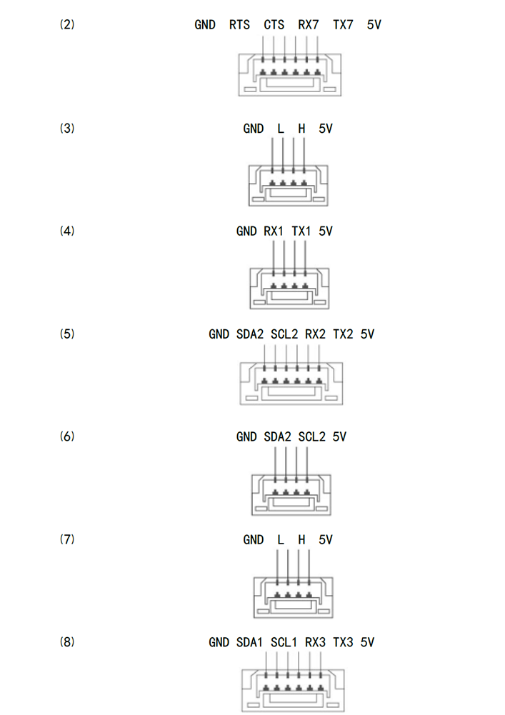
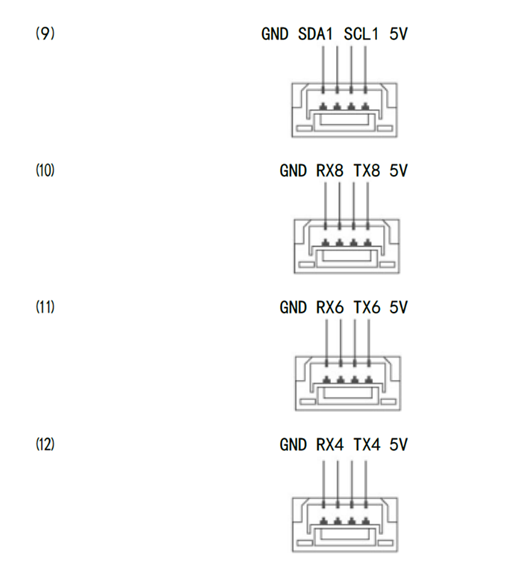
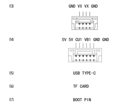
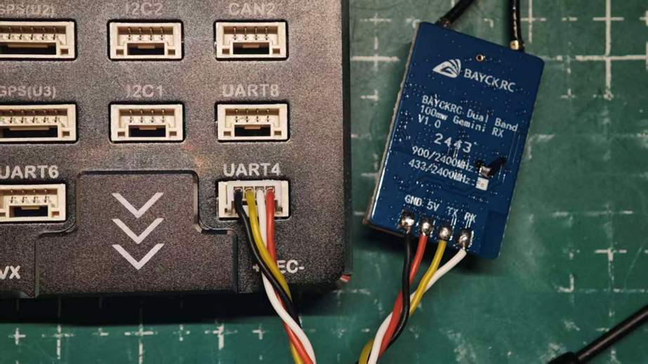
For an ELRS or TBS CRSF receiver, connection to UART4 on the flight controller is recommended.
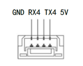
Connect receiver R (or RX) to flight controller TX4, and receiver T (or TX) to flight controller RX4.
Connect receiver V (or 5V) to flight controller 5V, and receiver G (or GND) to flight controller GND.
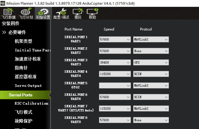
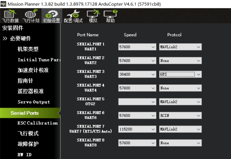
After wiring, configure SERIAL PORT4 on the ground station Serial Ports page as shown below.
2.1 Radio Receiver Wiring and Configuration
For an SBUS receiver, connect receiver S (or SBUS) to flight controller RX4, receiver V (or 5V) to flight controller 5V, and receiver G (or GND) to flight controller GND.
On the Serial Ports page, set Speed under SERIAL PORT4 to 57600.
2.2 GPS Module Wiring and Configuration
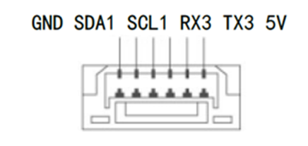
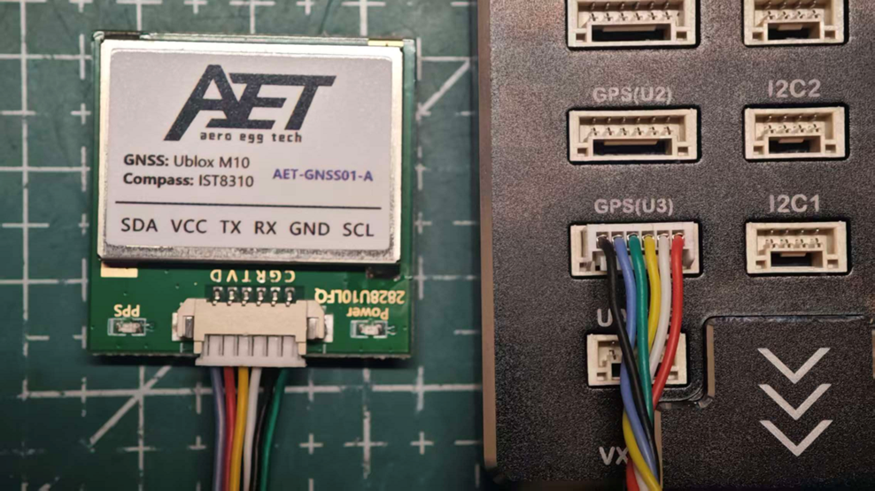
Connect the GPS module to the recommended GPS (U3) interface on the flight controller, which is UART3. Connect GPS R (or RX) to flight controller TX3, and GPS T (or TX) to flight controller RX3.
Connect GPS V (or 5V) to flight controller 5V, and GPS G (or GND) to flight controller GND.
Connect GPS SCL to flight controller SCL1 and GPS SDA to flight controller SDA1 for the compass integrated into the GPS module.
After wiring, configure SERIAL PORT3 on the ground station Serial Ports page as shown below.
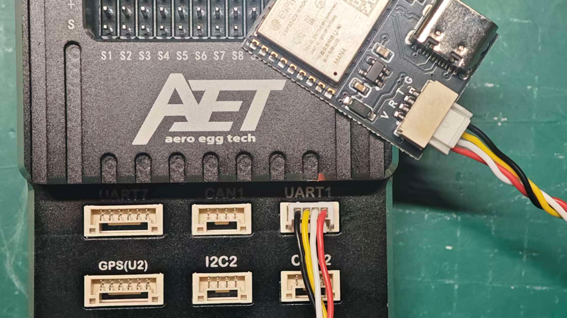
2.3 Wi-Fi Telemetry Link Module Wiring and Configuration
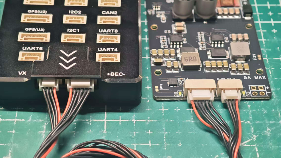
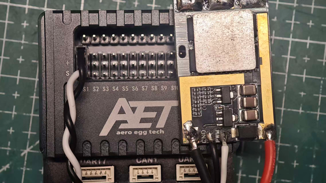
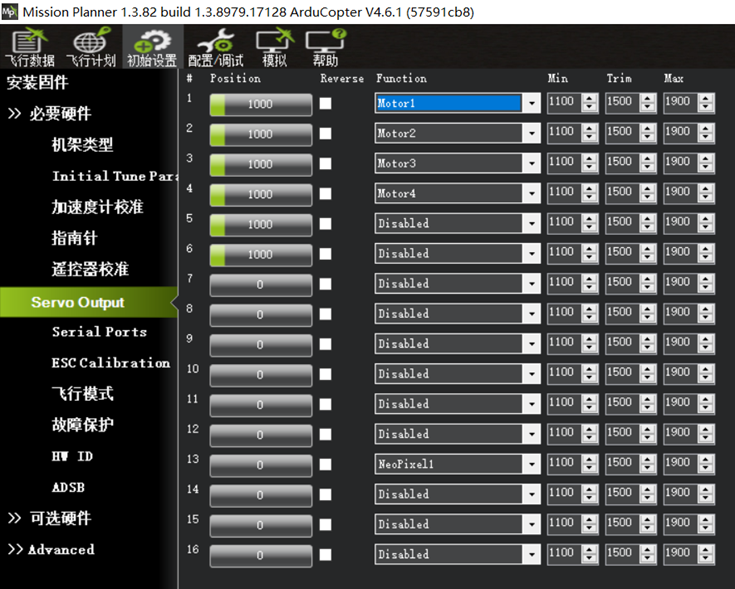
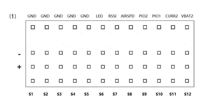
2.4 ESC Module Wiring and Configuration An ESC signal cable normally uses a 2.54 mm 3-pin Dupont connector. The dark wire is generally G (GND) and connects to the corresponding S1-S12 output ground on the flight controller. The light-colored or white wire is the ESC control signal S. Some ESCs include a built-in 5V BEC; when powered, the center 5V wire can conflict with the flight controller’s integrated 5V servo BEC. Disconnect the 5V wire from this type of ESC signal cable before connecting it to the flight controller. Configure the corresponding custom settings on the flight controller Servo Output page.