Chapter 3: Basic Configuration and Tuning
Section 1: Ground Station Connection Open MissionPlanner.
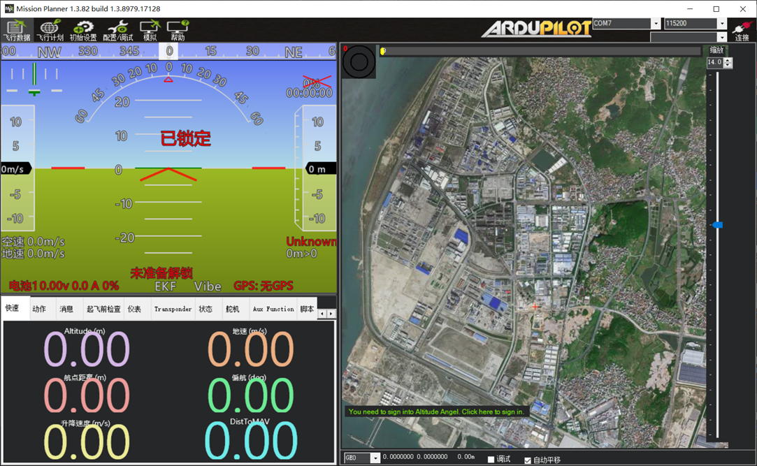
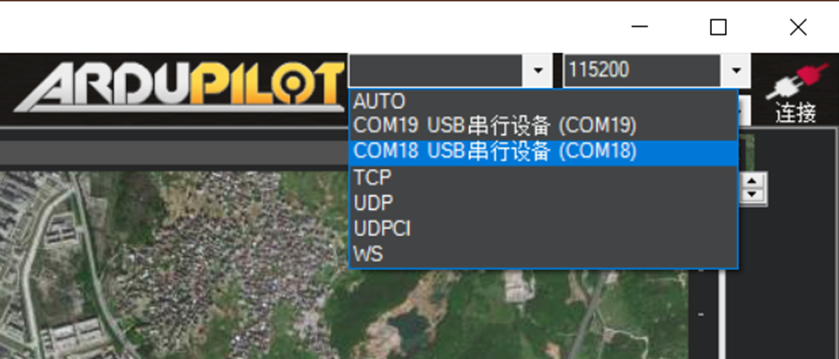
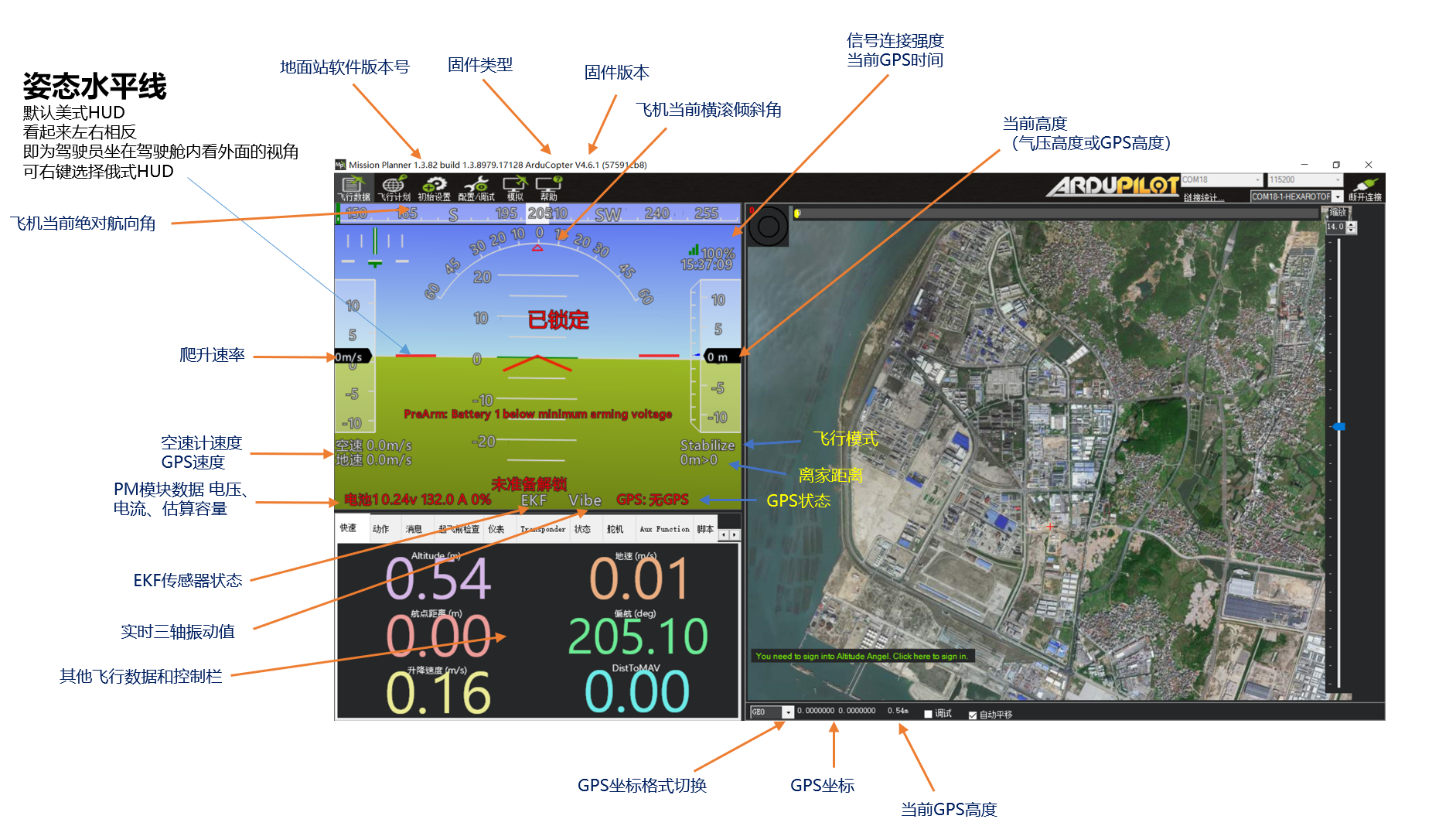
Connect the flight controller to the computer with a Type-C data cable. In the upper-right corner of MP, select the port assigned to the flight controller, as shown below:
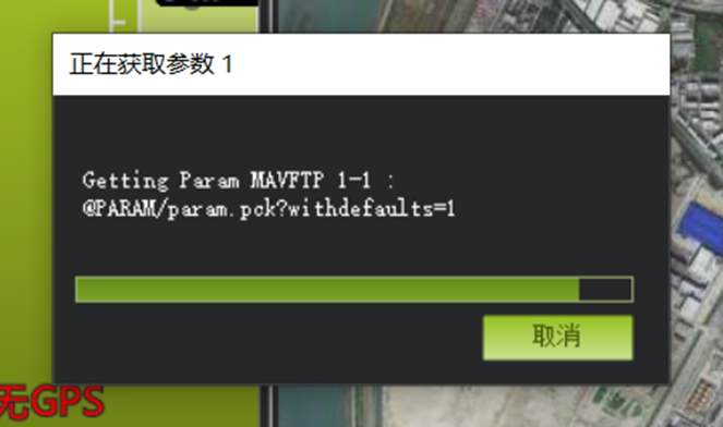
Click Connect and wait several seconds while the software reads data from the flight controller.
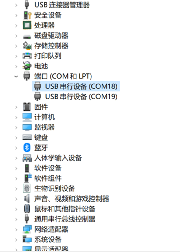
If the flight controller does not appear in the port drop-down menu after USB is connected, confirm that the computer has recognized the flight controller driver and assigned a port.
Check the Ports section in Device Manager. If no port number is assigned, install the appropriate driver.
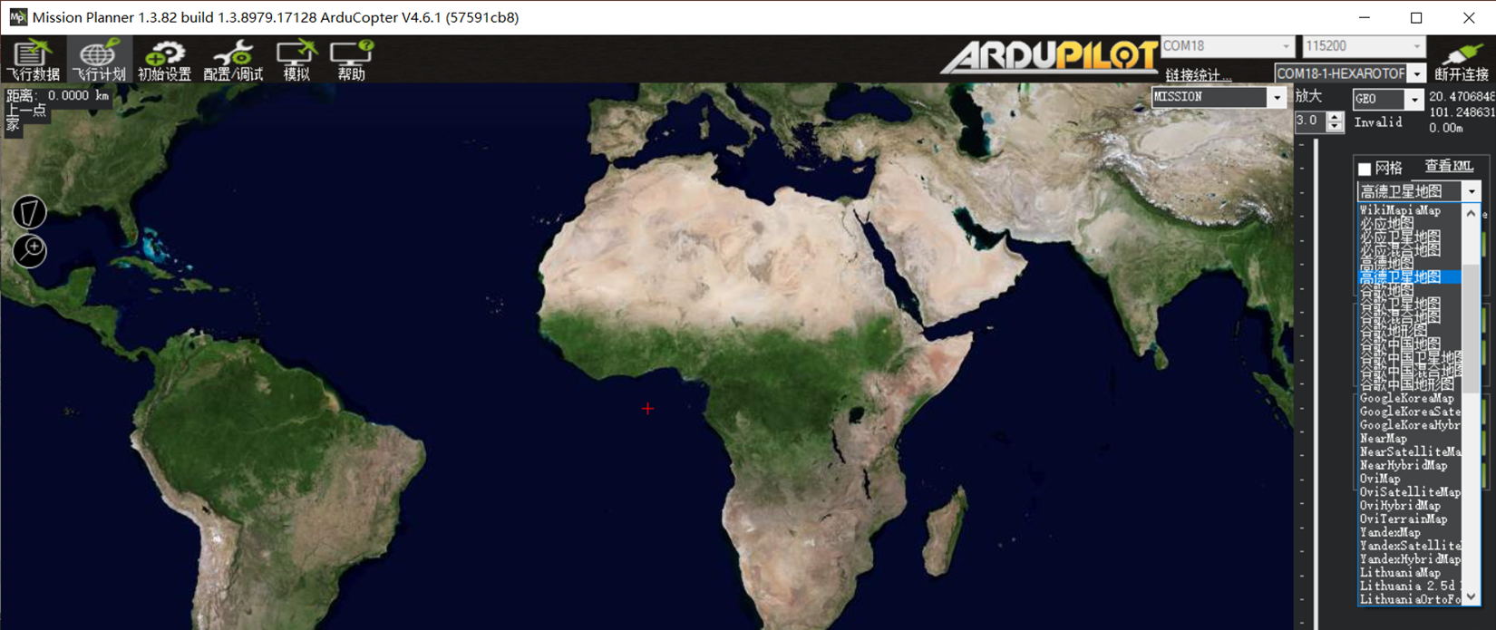
If live satellite imagery does not load, open the Flight Plan page and select a map source on the right. AMap Satellite is generally recommended. After selecting it, close and restart MissionPlanner; the ground station will then load AMap Satellite imagery online.
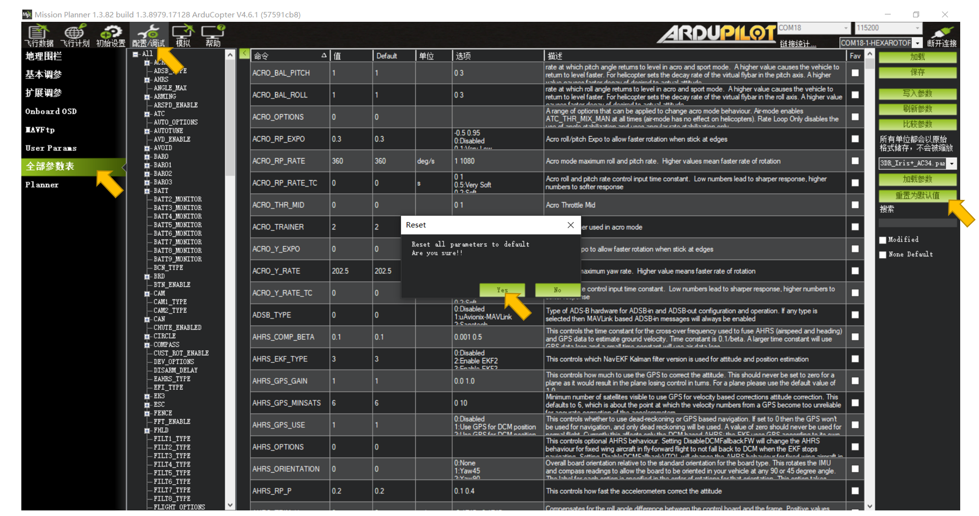
After flashing new firmware, it is strongly recommended to perform Reset to Default Parameters once before configuration.
Navigate to CONFIG/TUNING -- Full Parameter List -- Reset to Default Parameters.
Click the command once. When the ground station requests confirmation, click Yes.
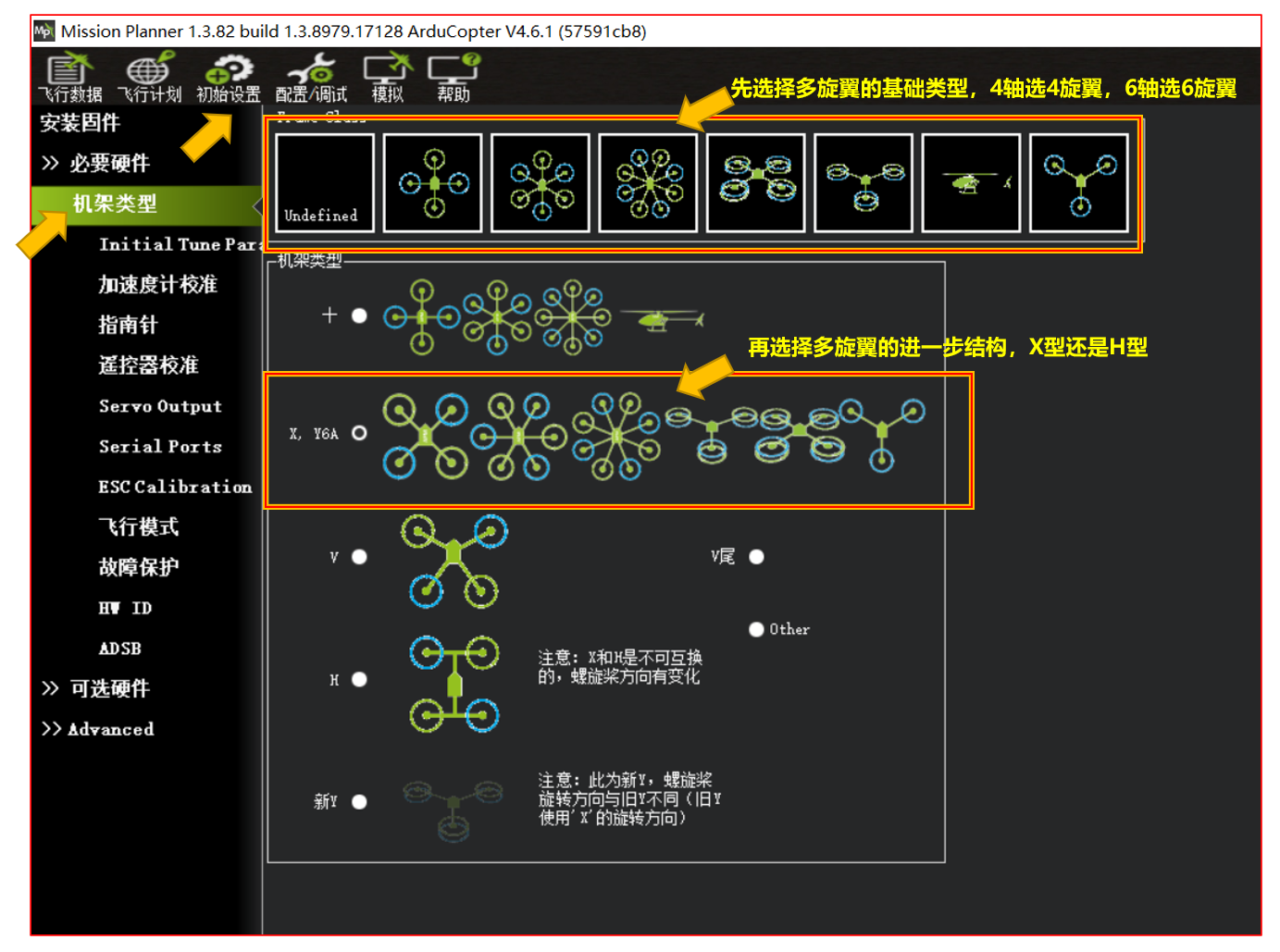
Section 2: Frame Type Selection Open Initial Setup -- Frame Type. Select the required configuration, such as X, Y6A, a conventional X quadcopter, hexacopter, octocopter, or X8.
Tuning Process Instructions: Apply the basic parameter preset so the flight controller can generate initial PID parameter values.
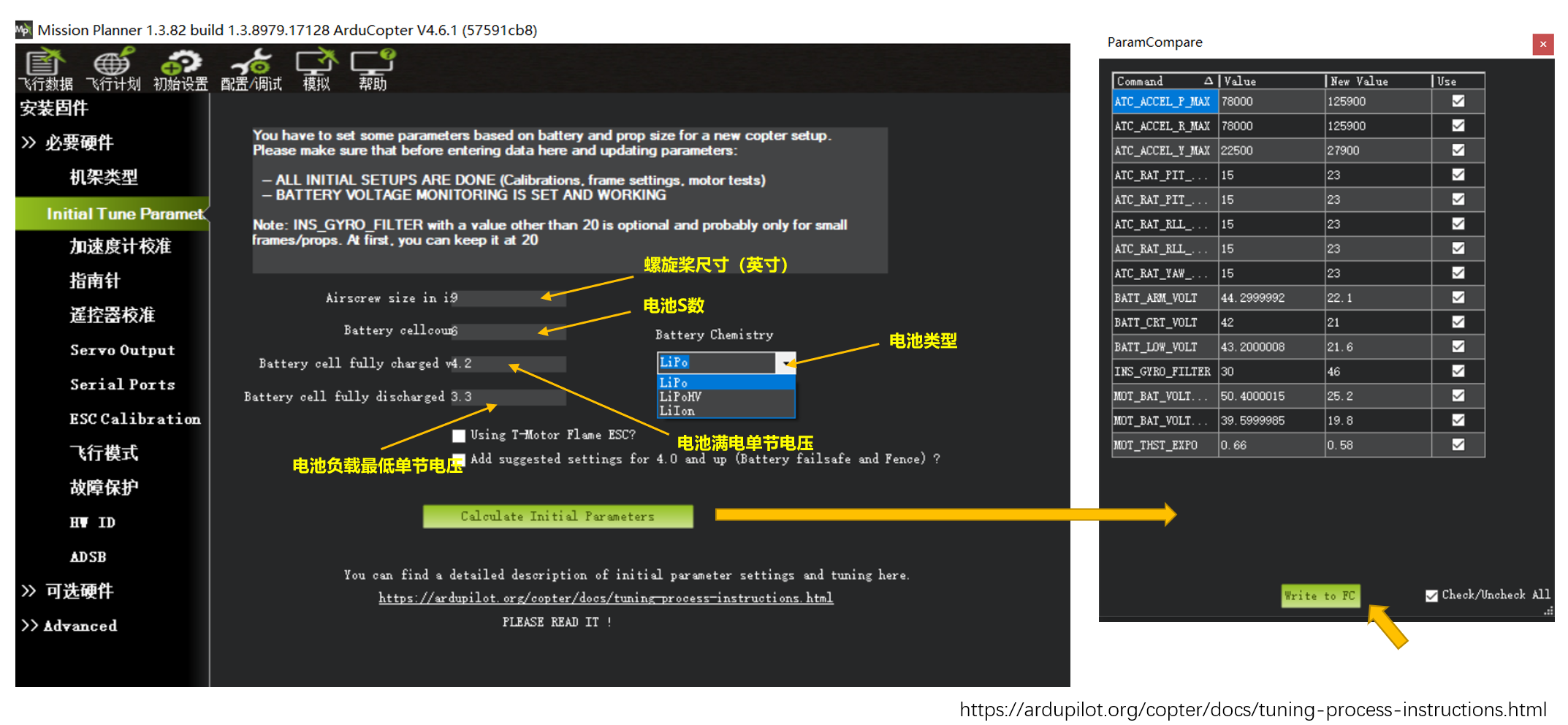 https://ardupilot.org/copter/docs/tuning-process-instructions.html
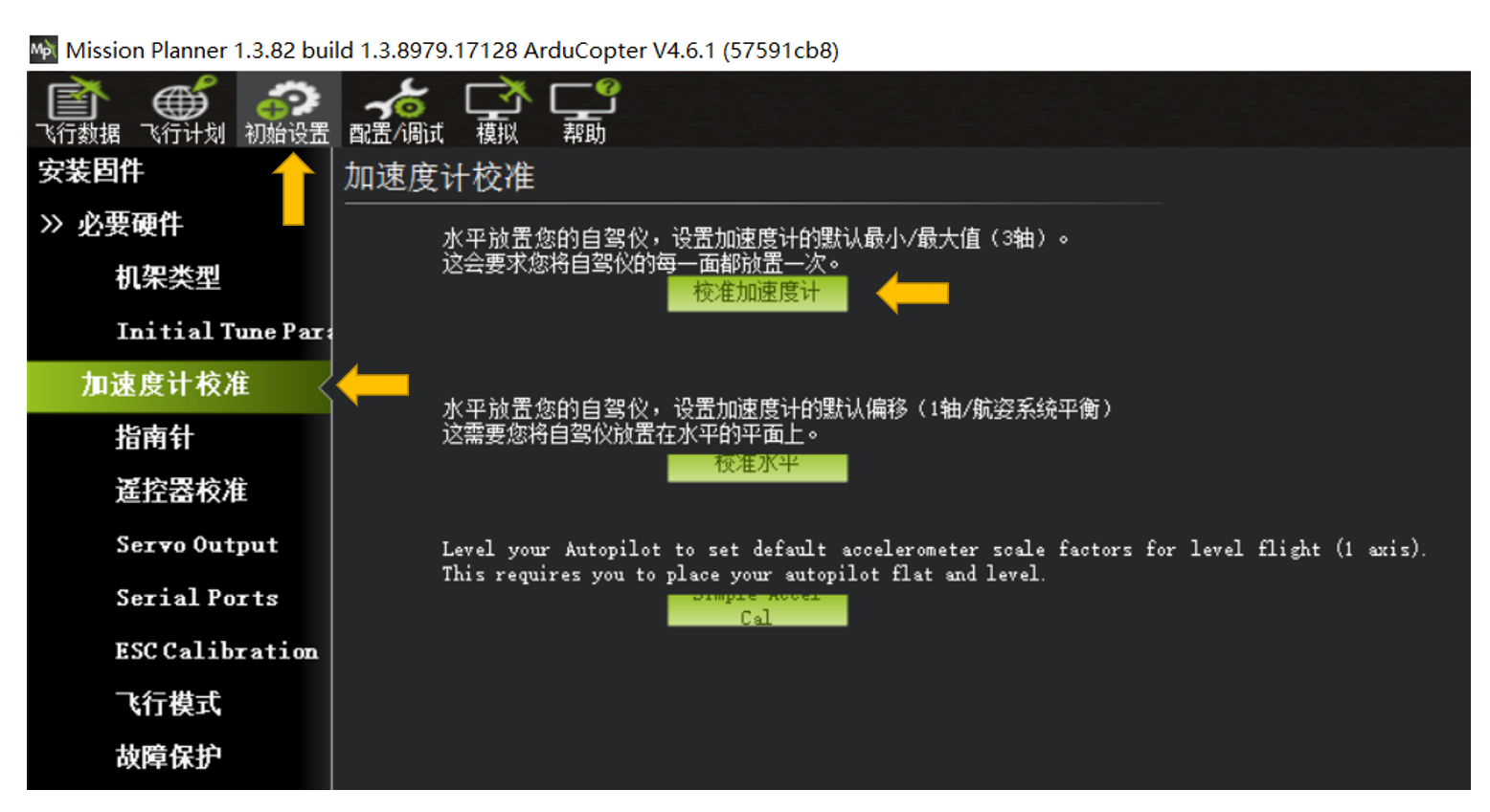
Section 3: Accelerometer Calibration
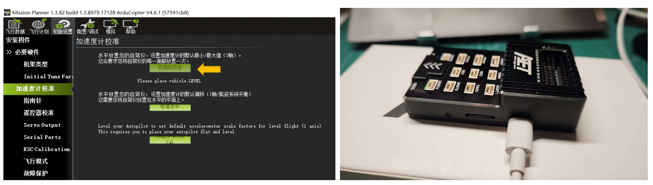
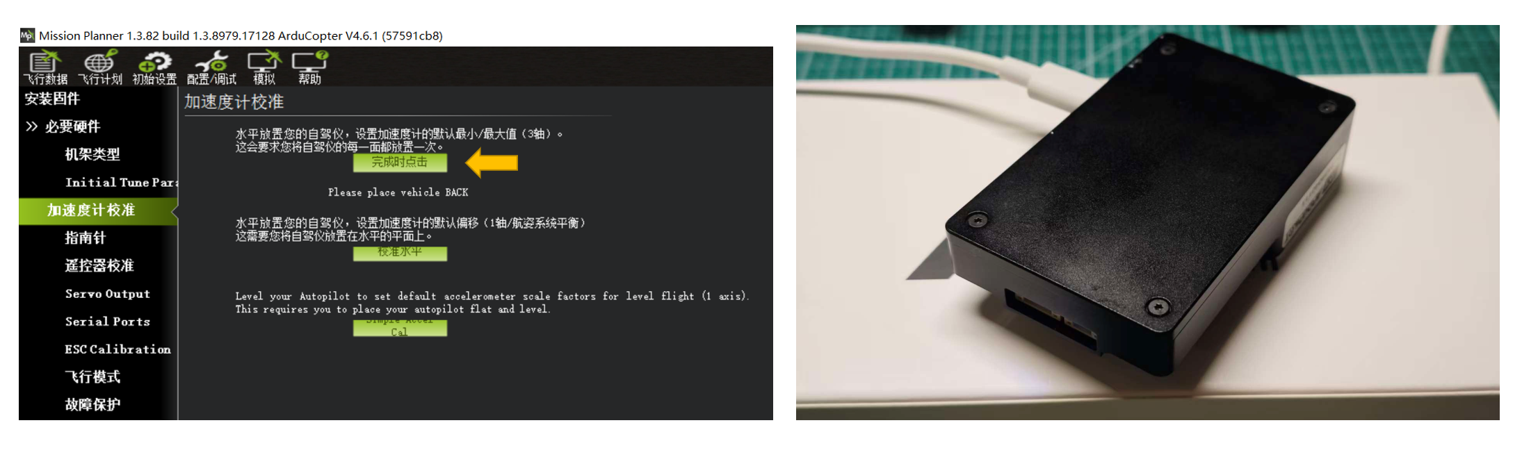
Click Calibrate Accelerometer and follow the software prompts. Place the flight controller on each of its six faces as instructed to complete the calibration.
Please place vehicle LEVEL -- Accelerometer calibration with the bottom face down
Please place vehicle LEFT -- Accelerometer calibration with the left face down
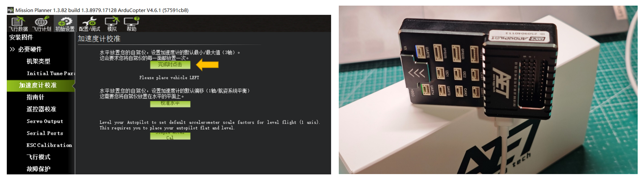
Please place vehicle RIGHT -- Accelerometer calibration with the right face down
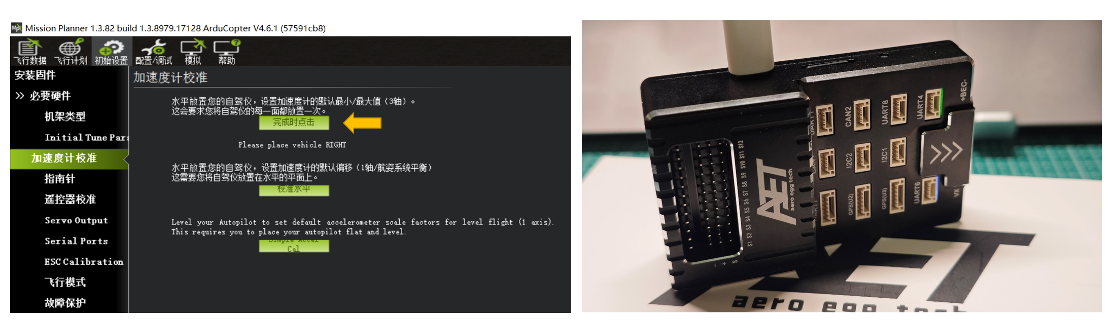
Please place vehicle NOSEDOWN -- Accelerometer calibration with the front face down
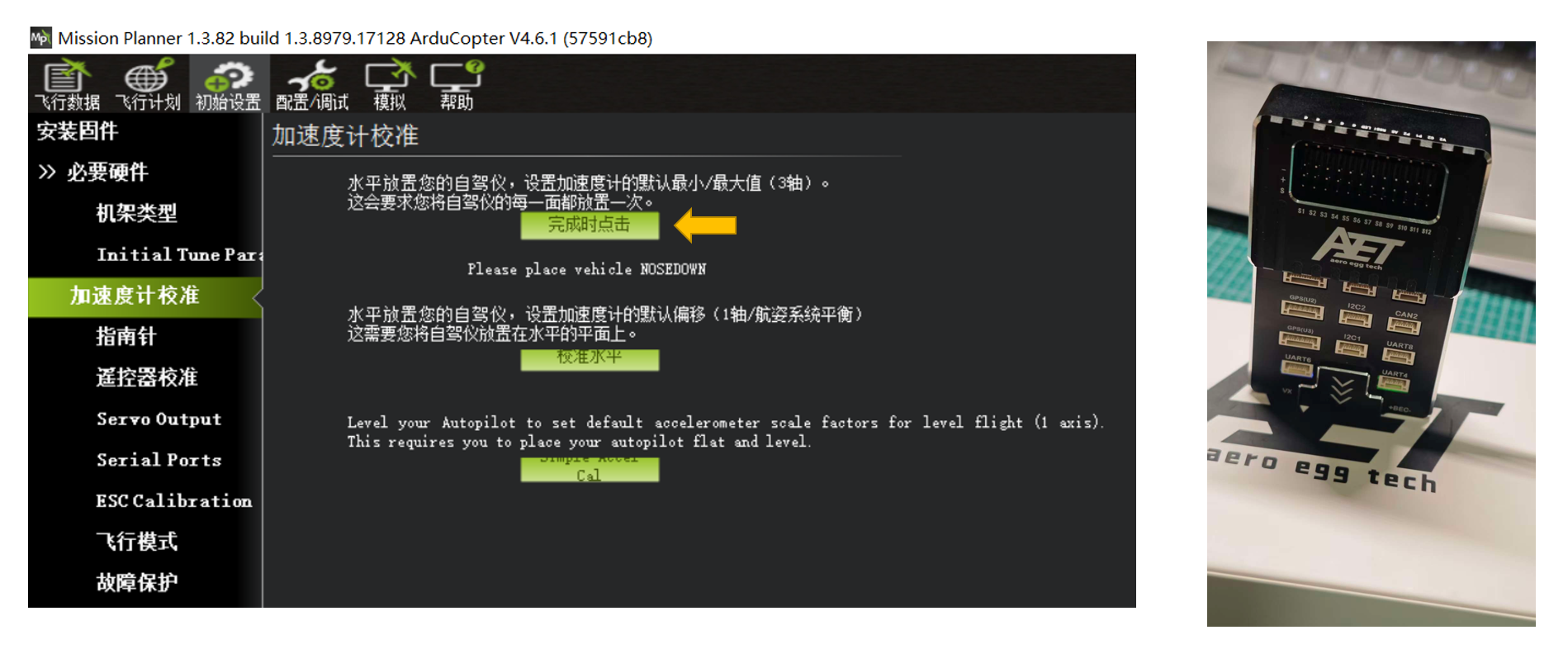
Please place vehicle NOSEUP -- Accelerometer calibration with the rear face down
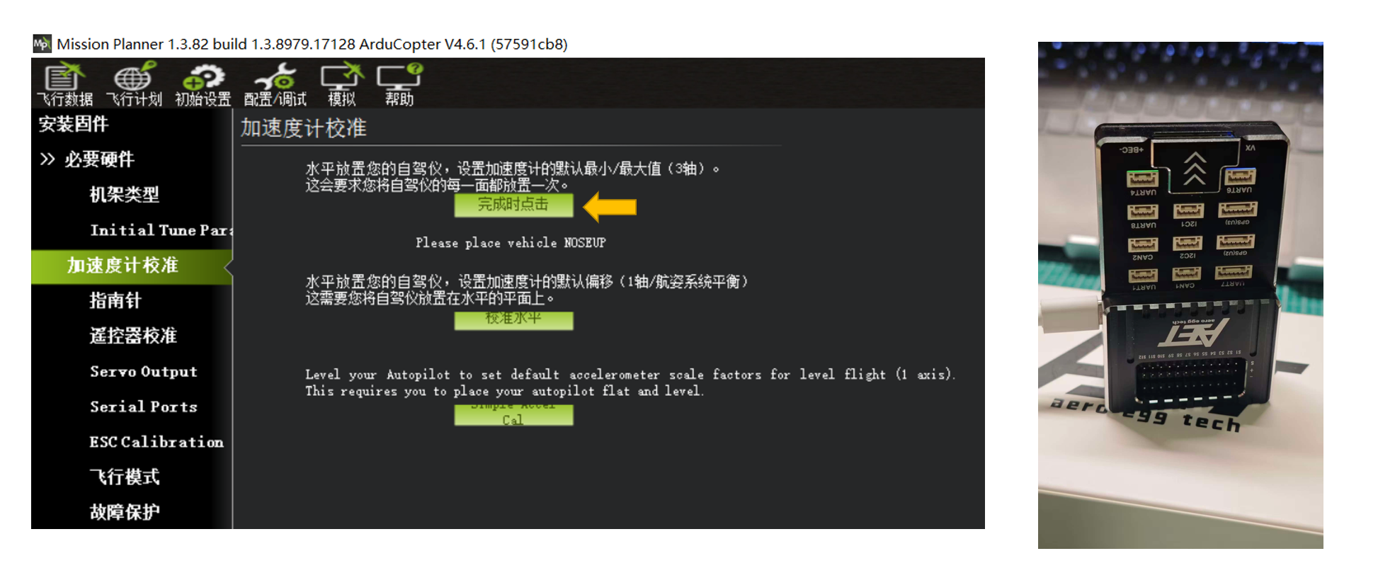
Please place vehicle BACK -- Accelerometer calibration with the top face down
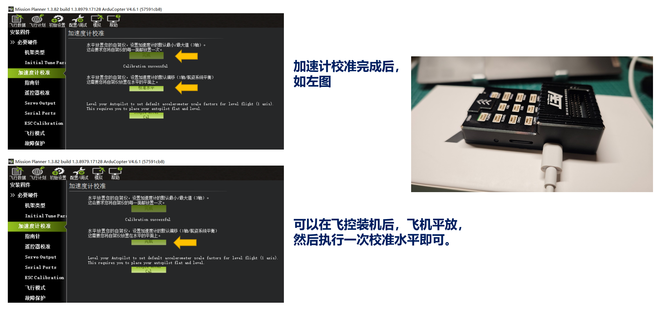
Level Calibration:
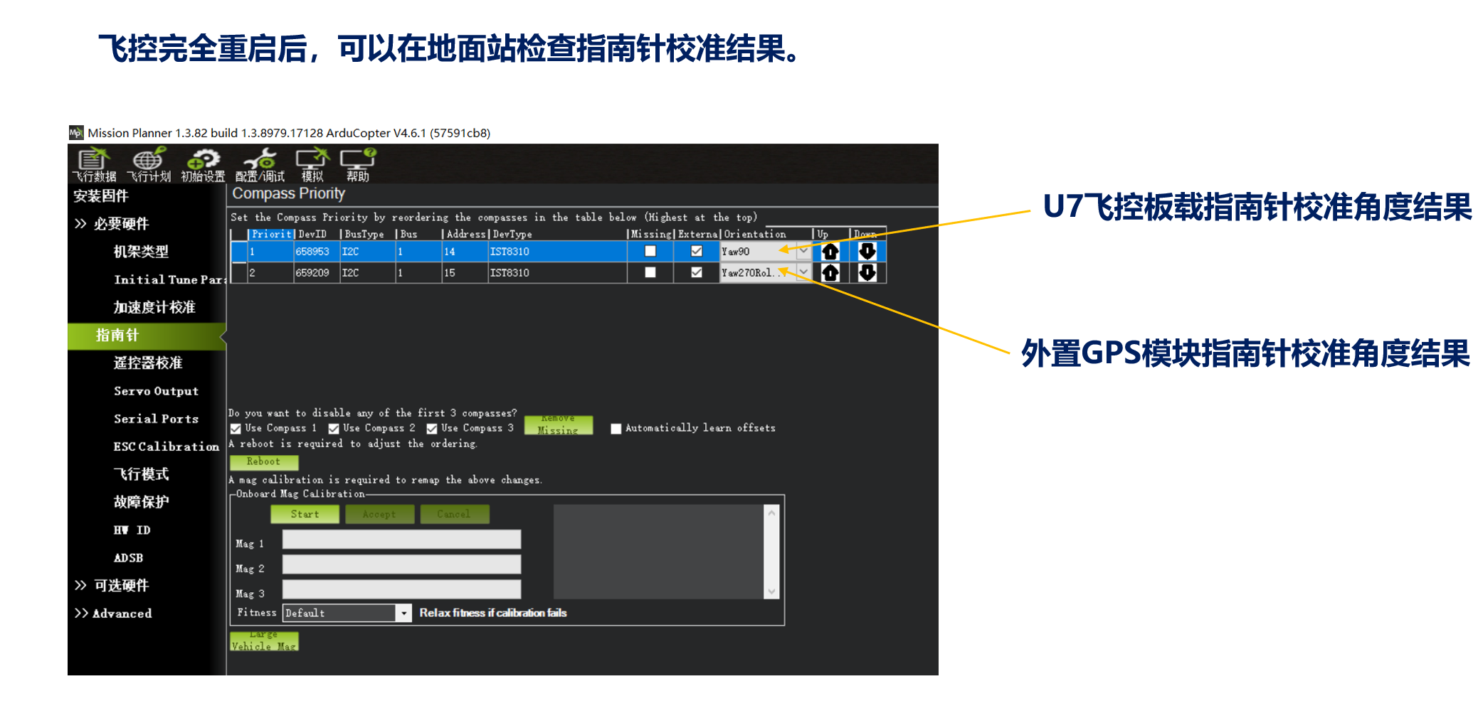
Section 4: Compass Calibration External GPS compass installation: Use a GPS mount and keep the module at least 10~15CM away from the PM power board and flight controller. The GPS module may be installed in any orientation; after calibration, the orientation offset relative to the flight controller is determined automatically.
Do not calibrate the compass in an area where metal or electrical equipment can disturb the magnetic field, including inside metal-framed buildings or within 20~30 meters of metal-framed shelters, tall buildings, high-power generators, or power equipment. Magnetic interference may cause calibration failure or inaccurate results.
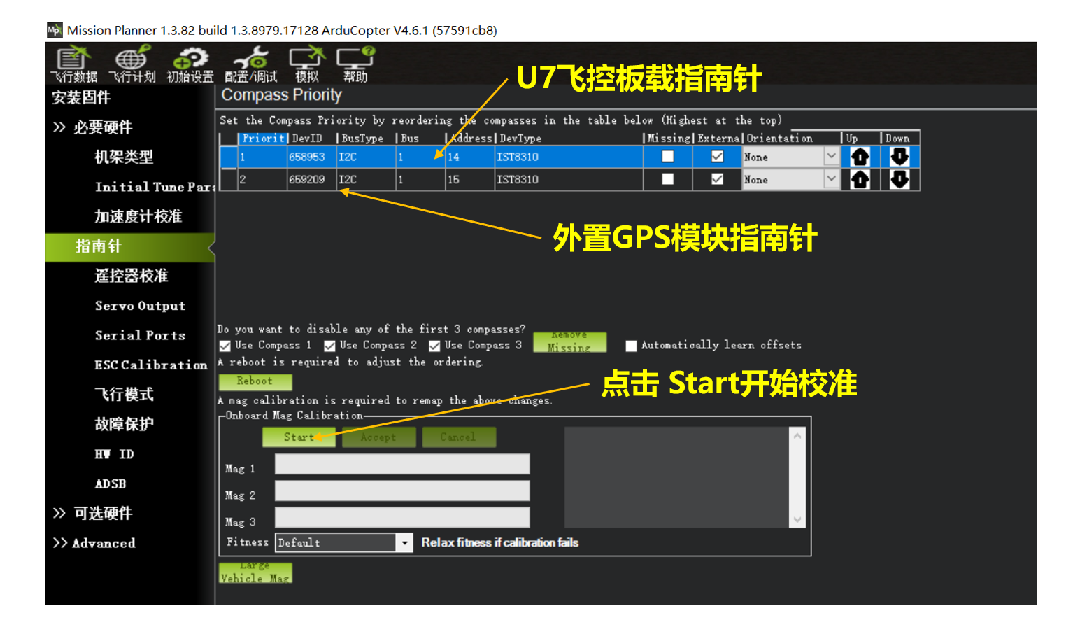
Compass Calibration Procedure:
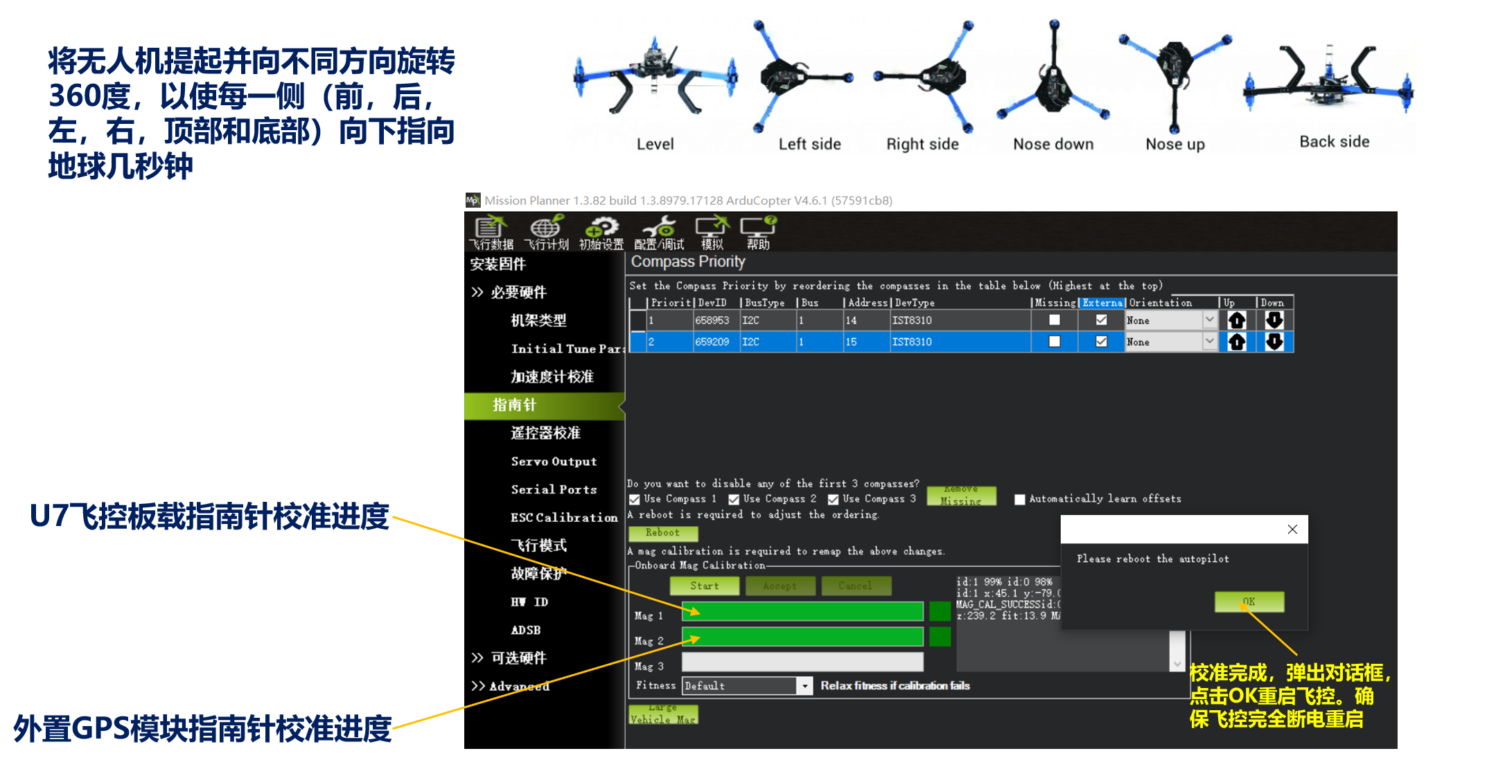
Confirming the Result:
Section 5: Radio Transmitter Calibration
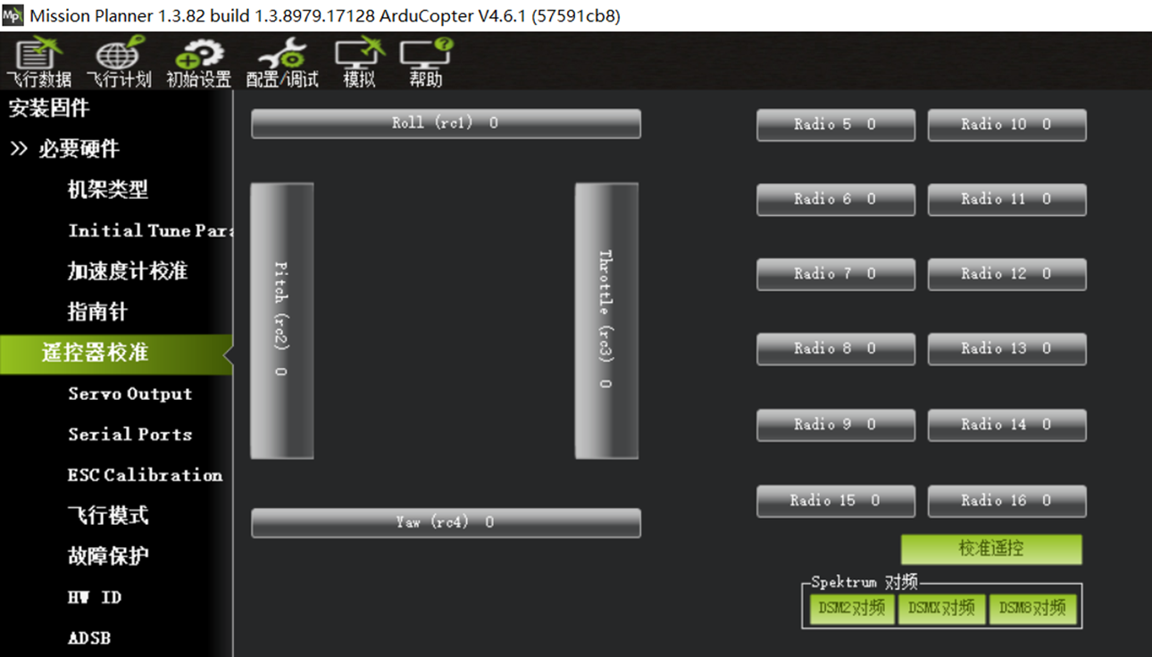
If the radio transmitter is powered on and paired with the receiver but the receiver wiring or serial-port configuration is incorrect, the Radio Calibration page will not show channel activity or values for channels 5~16, as shown below.
When the receiver is wired correctly and the corresponding serial port is configured correctly, green input bars are visible for all channels.
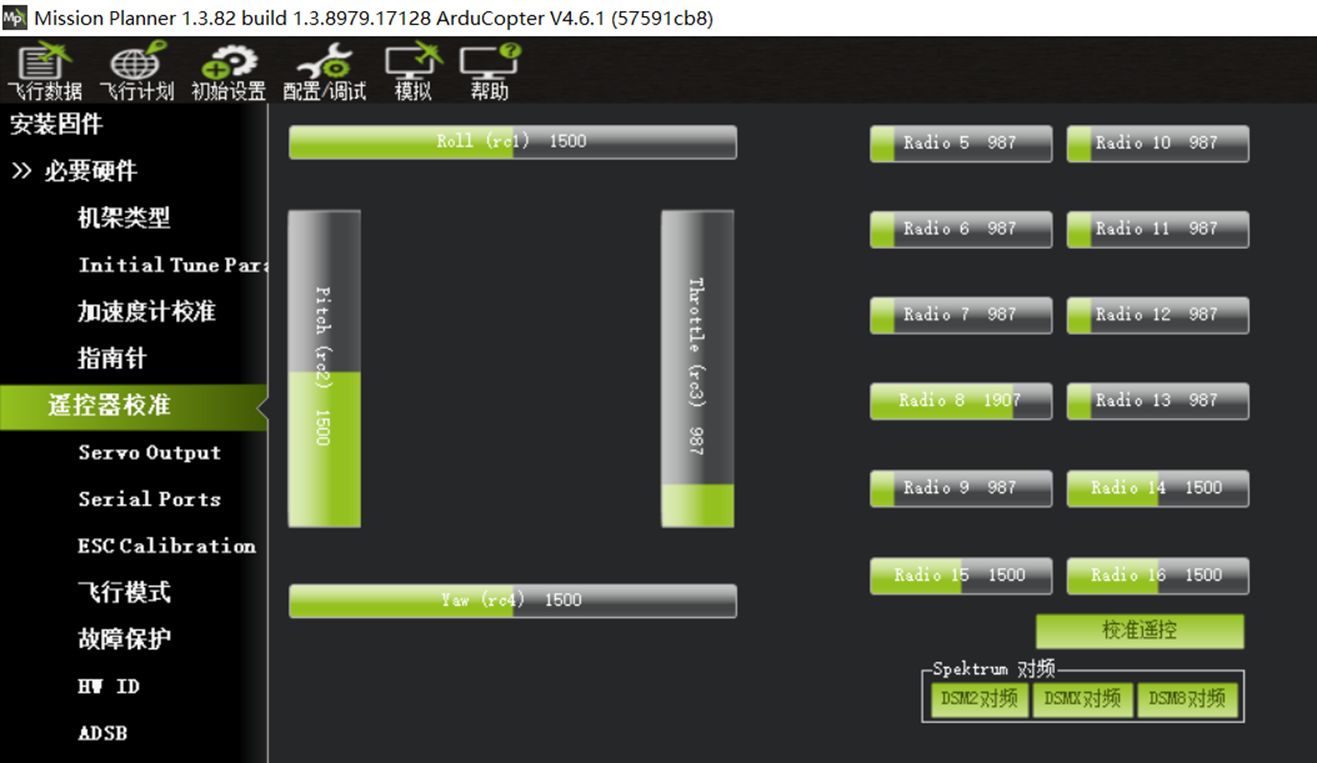
You can now calibrate the radio transmitter sticks and auxiliary switch channels.
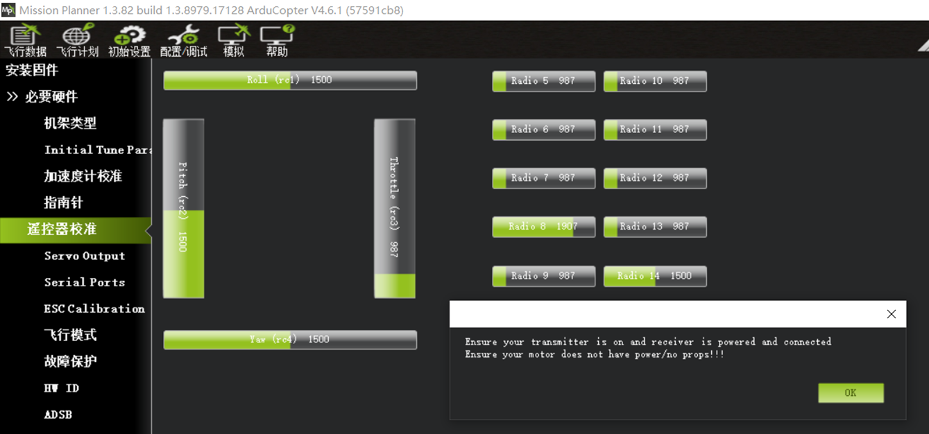
Click Calibrate Radio. The dialog Ensure your transmitter is on and receiver is powered and connected. Ensure your motor does not have power/no props!!! reminds you to confirm the throttle-channel direction and ensure that the motors are unpowered and all propellers are removed. Click OK, as shown below:
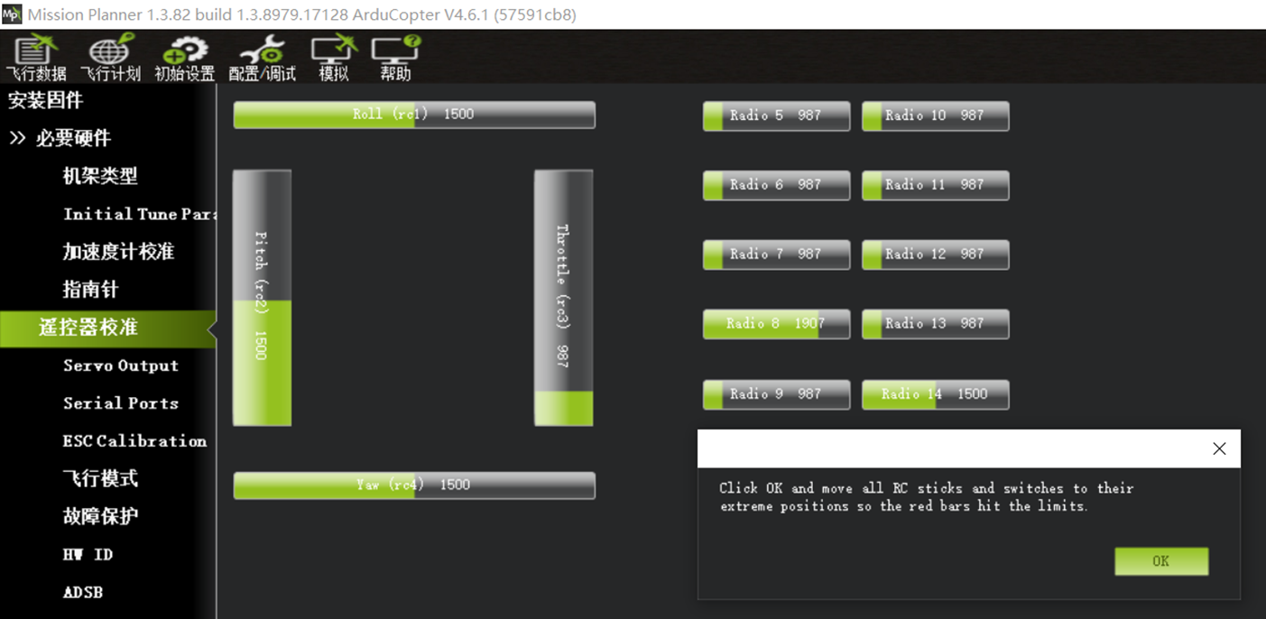
The dialog Click OK and move all RC sticks and switches to their extreme positions so the red bars hit the limite instructs you to move every stick, switch channel, and six-position switch through its full range so the red bars record the minimum and maximum outputs. Click OK, as shown below:
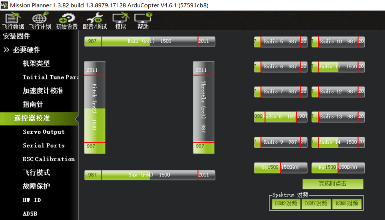
Move all sticks, switch channels, and the six-position switch through their full ranges. Confirm that the red bars capture the minimum and maximum output for each channel, then click Click when done, as shown below.
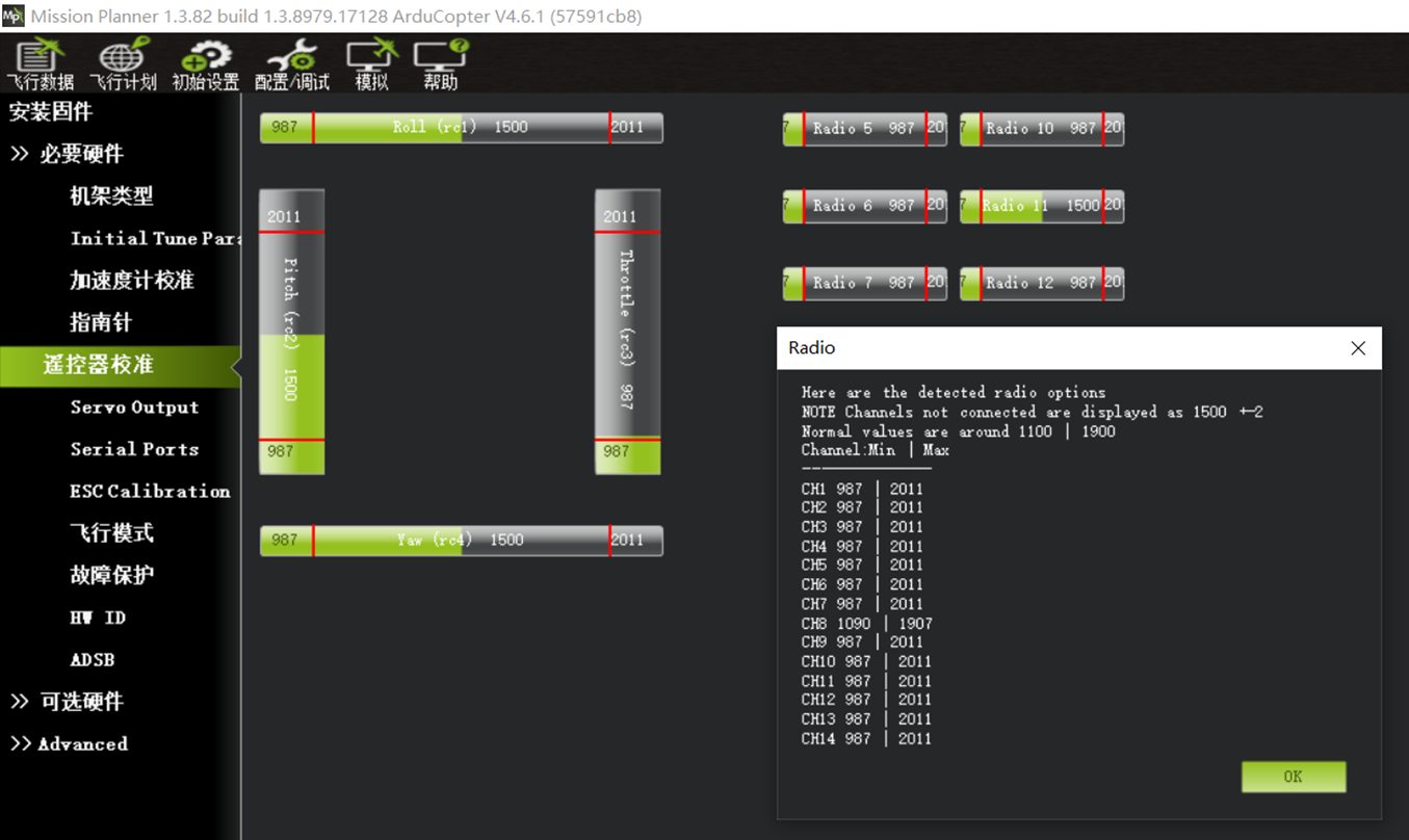
After clicking OK, a dialog displays the recorded minimum and maximum input values for each channel. Click OK, as shown below:
Section 6: Motor Rotation Direction and ESC Order
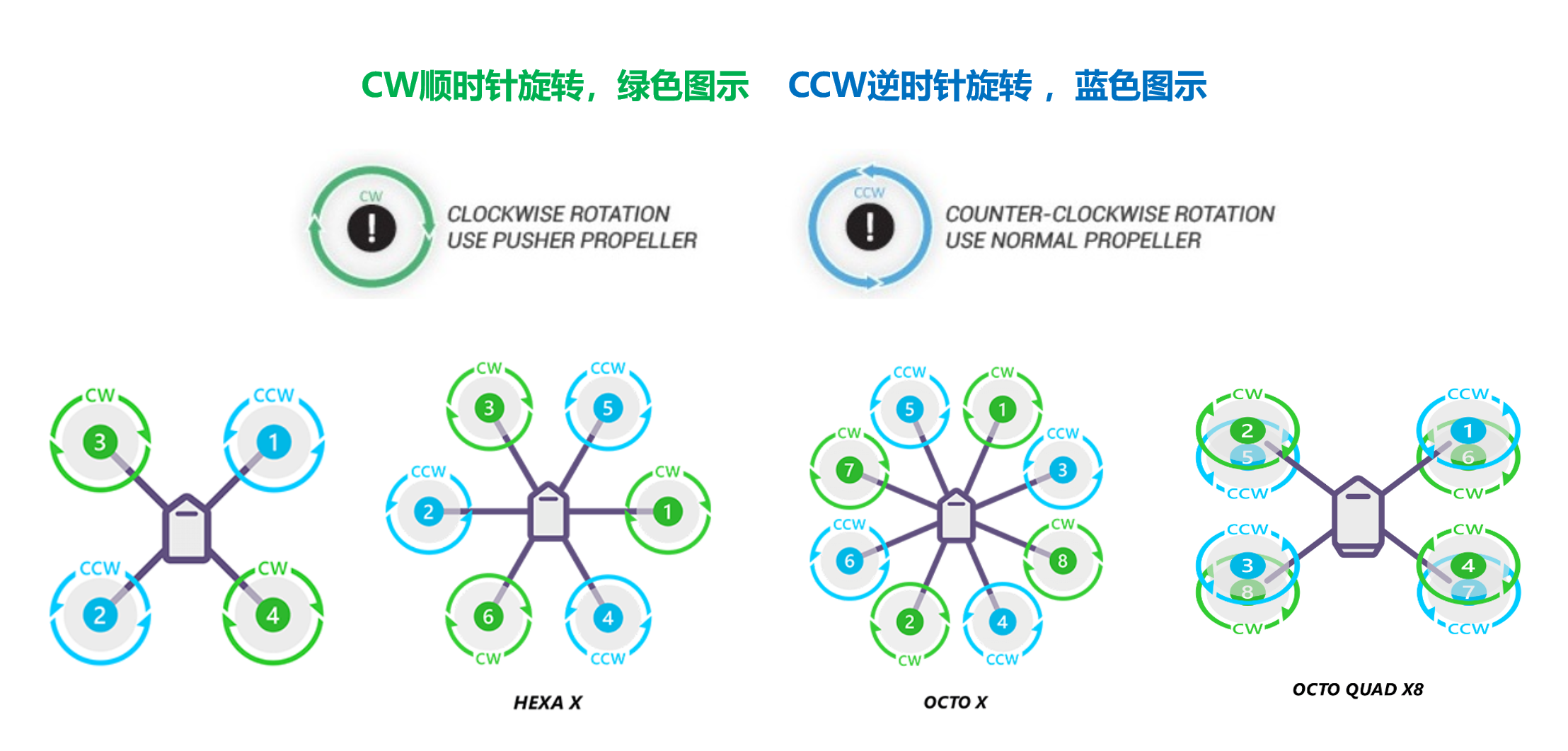
Motor and ESC Connections - X4
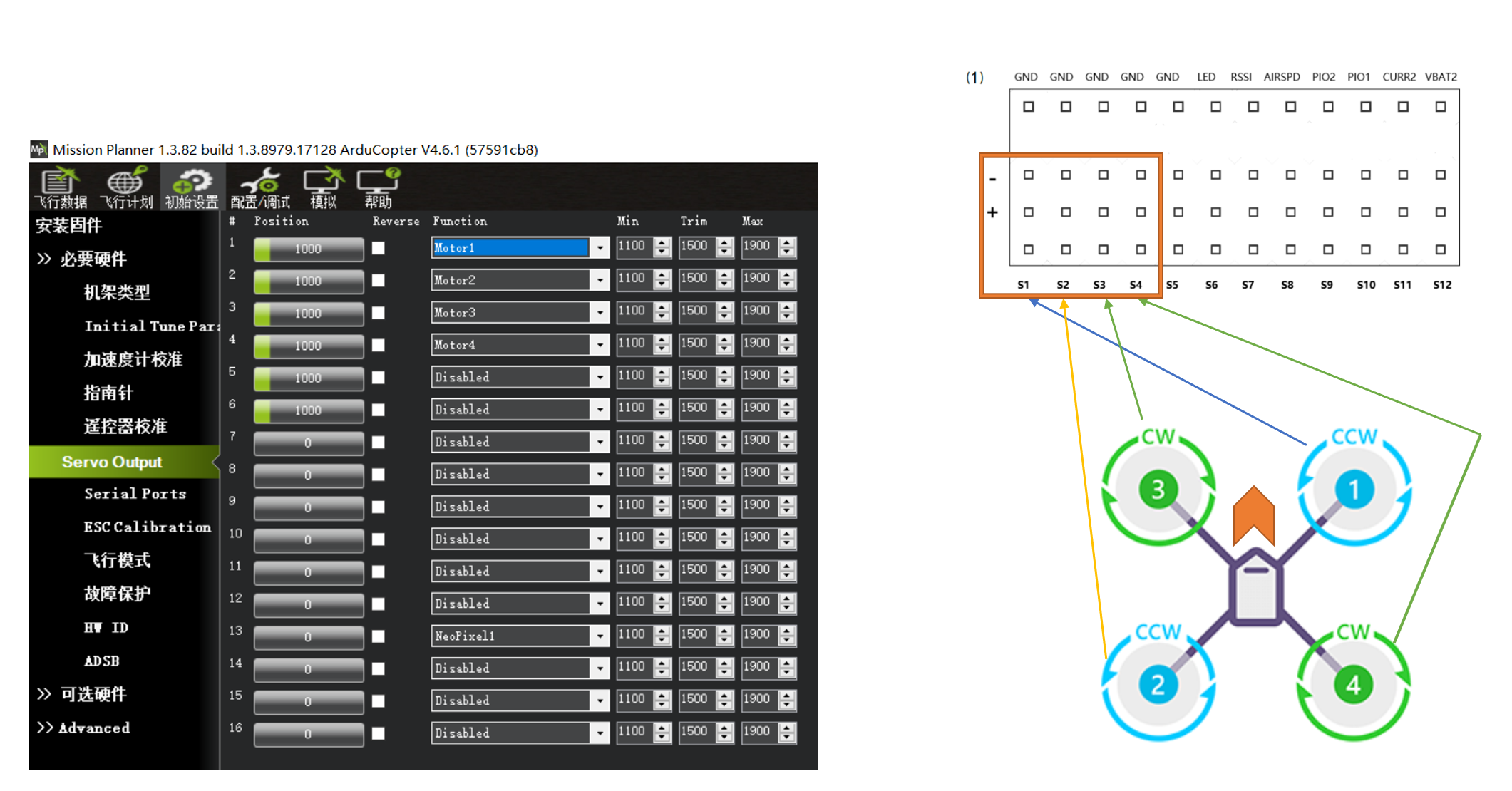
Motor and ESC Connections - Hexacopter
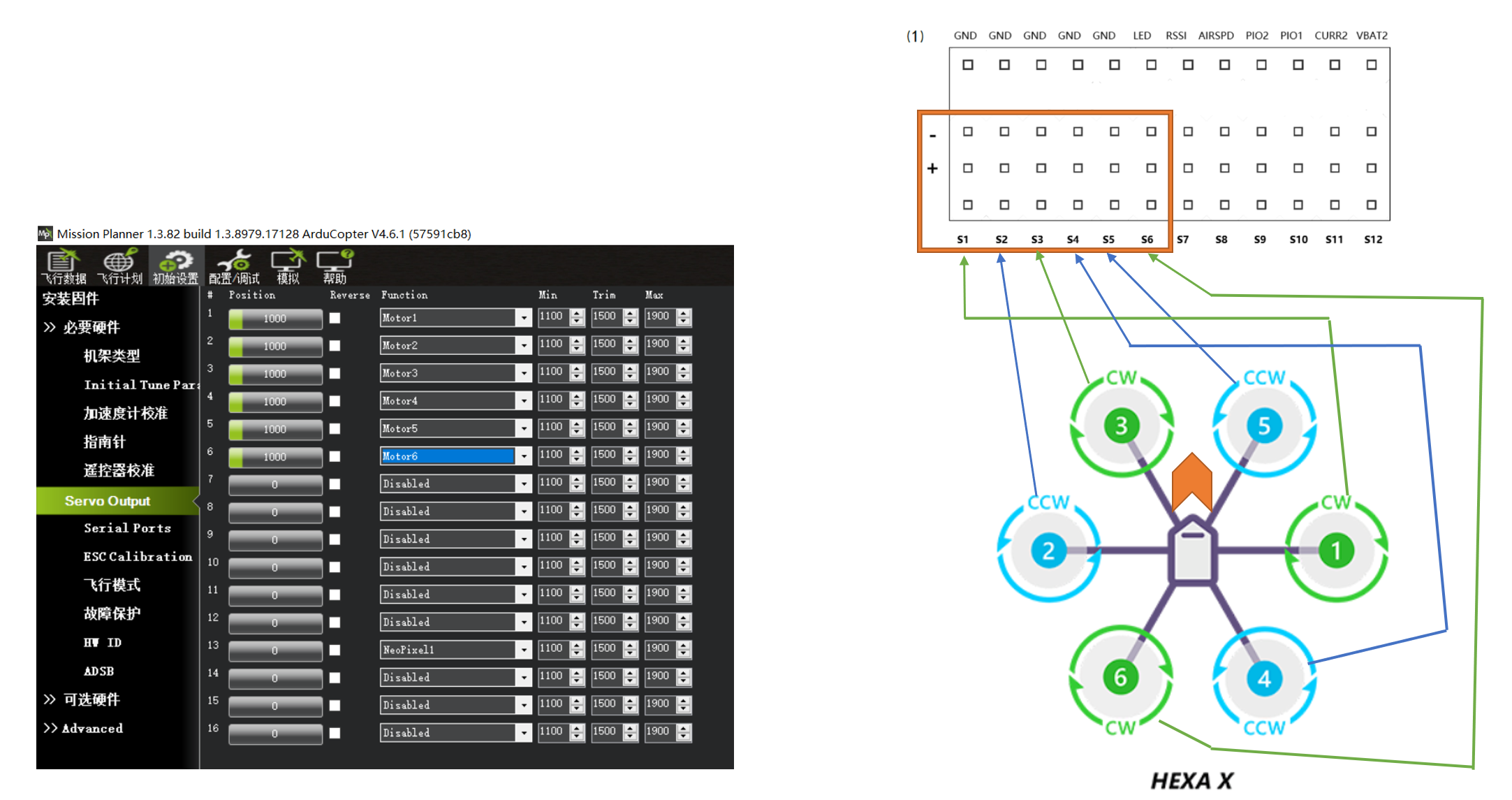
Motor and ESC Connections - Octocopter
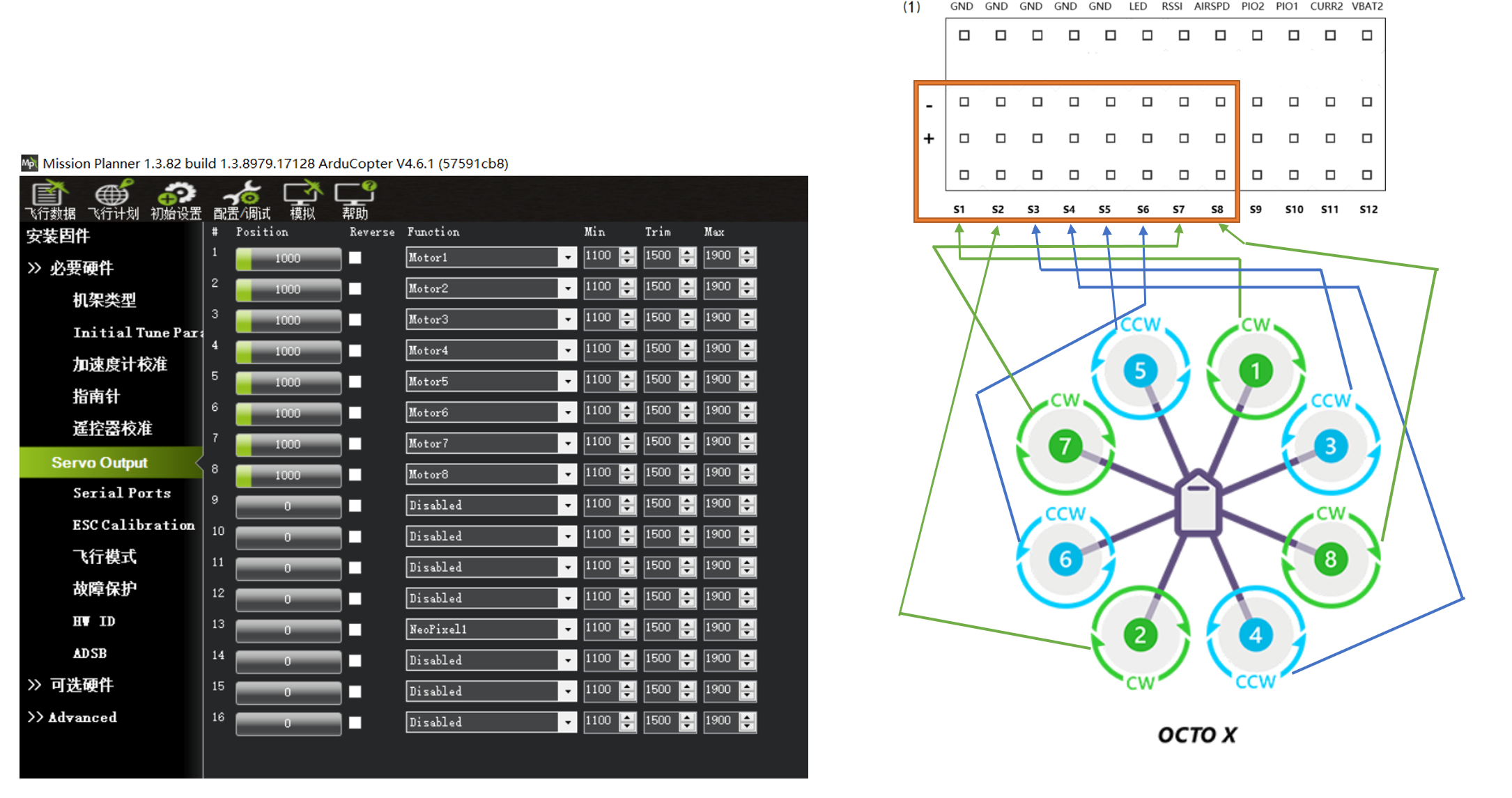
Motor and ESC Connections - X8
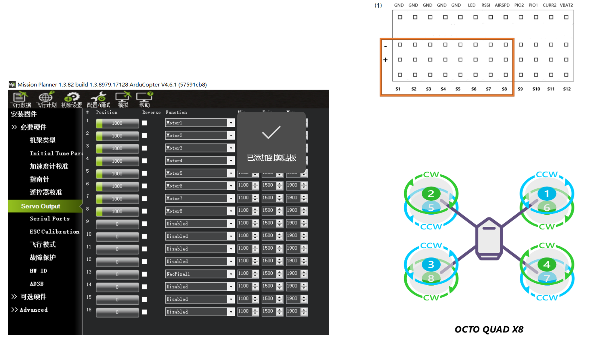
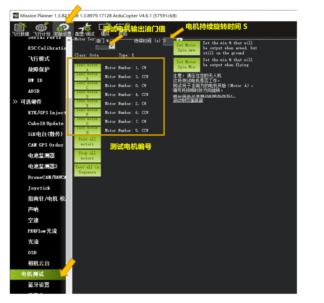
Section 7: Motor Test: Use Mission Planner Motor Test to Verify Motor Numbers

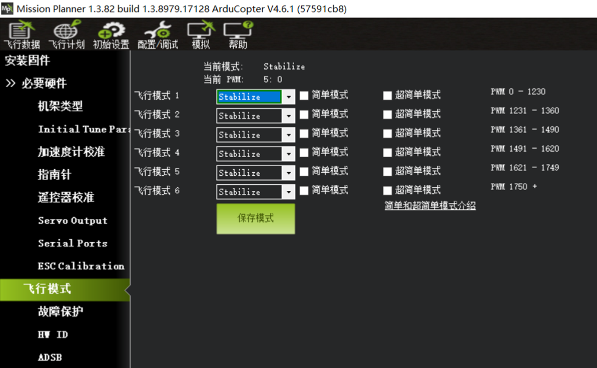
Section 8: Flight Modes