Chapter 2: Flight Controller Wiring
The AeroEgg AET F405A WING flight controller wiring diagram is shown below: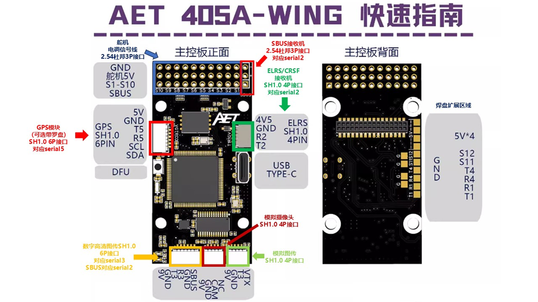
Common peripherals include GPS positioning modules, SBUS receivers, ELRS receivers/TBS CRSF receivers, digital air units (including DJI O3, O4, and Vista; Caddx Avatar series; and open-source OpenIPC HD video systems), airspeed sensors, electronic compasses, and similar devices.
GPS modules, SBUS receivers, ELRS receivers, TBS CRSF receivers, telemetry modules, and digital air units are serial peripherals. The compass in a GPS module and an analog airspeed sensor are I2C bus peripherals.
Connect an analog I2C airspeed sensor to the flight controller SDA and SCL pins. See Section 12 of Chapter 4 for details.
Serial-bus receiver connection example:
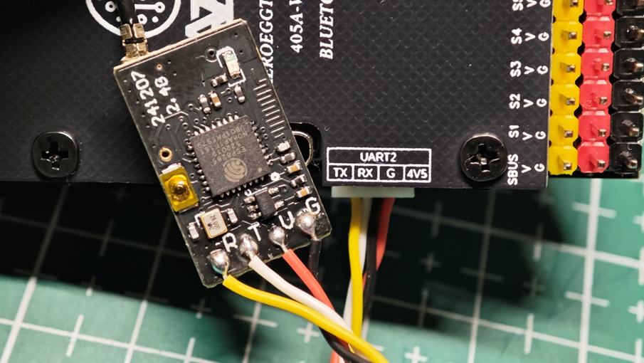
For an ELRS receiver or TBS CRSF receiver, we recommend connecting it to UART2 on the flight controller, as shown above.
Connect receiver R (or RX) to flight controller TX, and receiver T (or TX) to flight controller RX.
Connect receiver V (or 5V) to flight controller 4V5, and receiver G (or GND) to flight controller G.
After wiring, configure Port 2 as RCIN at 115200. Only one port may be configured as RCIN; otherwise, radio transmitter input will not respond.
GPS module connection example (including electronic compass)
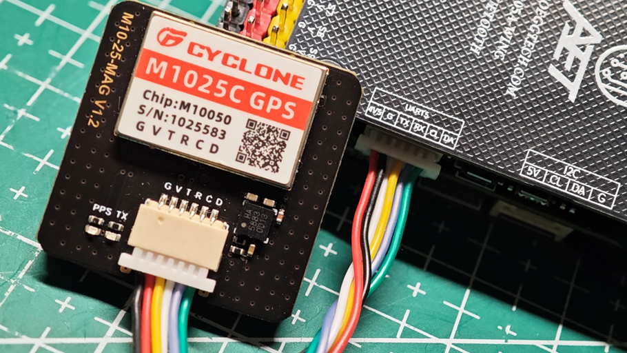
For a GPS module, we recommend connecting it to UART5 on the flight controller, as shown above.
Connect GPS R (or RX) to flight controller TX, and GPS T (or TX) to flight controller RX.
Connect GPS V (or 5V) to flight controller 4V5, and GPS G (or GND) to flight controller G.
Connect GPS C to flight controller CL and GPS D to flight controller DA. CL and DA are the I2C bus connections for the electronic compass integrated into the GPS module. A compass is optional on a conventional fixed-wing aircraft. If the GPS module has no compass, CL and DA do not need to be connected.
After wiring, configure Port 5 for GPS at a baud rate of 115200 in the ground station.
Digital air unit connection example
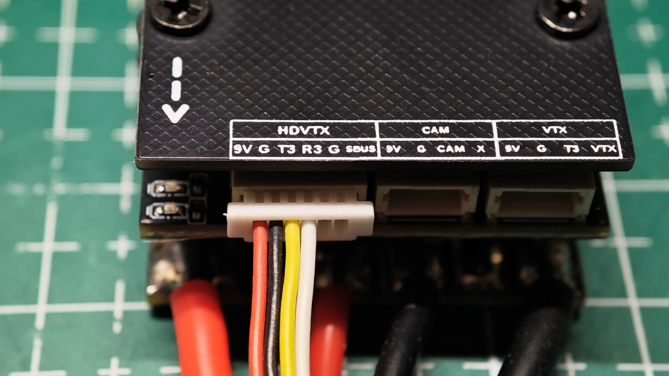
For a digital air unit, we recommend connecting it to the flight controller HDVTX connector (UART3), as shown above.
Connect air unit R (or RX) to flight controller T3, and air unit T (or TX) to flight controller R3 。 Connect air unit V to flight controller 9V, and air unit G (or GND) to flight controller G.
DJI air units include an SBUS receiver for binding to the DJI FPV2 radio transmitter. If you do not use a DJI FPV2 radio transmitter, disconnect the SBUS wire from this ribbon cable.
If you use a DJI FPV2 radio transmitter, keep the SBUS wire connected.
After wiring, configure the corresponding port in the ground station.
Servo connection example
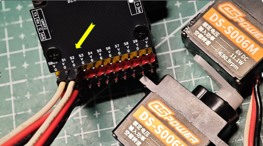
Servo leads normally use a 2.54 mm 3-pin Dupont connector. The dark wire is generally G (GND), the red or orange-red wire is the positive 5V servo supply V, and the white or orange-yellow wire is the servo control signal S. Connect the lead to the corresponding S1-S10 output and configure it on the flight controller Output page.
ESC signal wire connection example
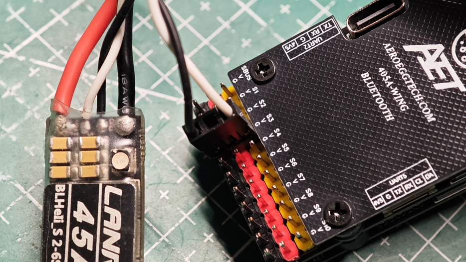 ESC signal leads normally use a 2.54 mm 3-pin Dupont connector. The dark wire is generally G (GND), and the light-colored or white wire is the ESC control signal S; connect these to the corresponding S1-S10 output. Some ESCs include a built-in 5V BEC. After the ESC is powered, the 5V output on the center wire may conflict with the flight controller onboard 5V servo BEC. Disconnect the 5V wire from this type of ESC signal lead before connecting it to the flight controller.
Configure the corresponding function on the flight controller Output page.