Chapter 3: Basic Configuration and Tuning
Section 1: Connect the Ground Station and Reset Default Parameters. Open the AGC configuration and tuning software.
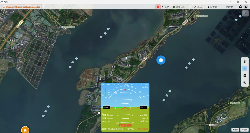
Connect the flight controller to the computer with a Type-C data cable. In the upper-right corner of AGC, select the port assigned to the flight controller, as shown below:
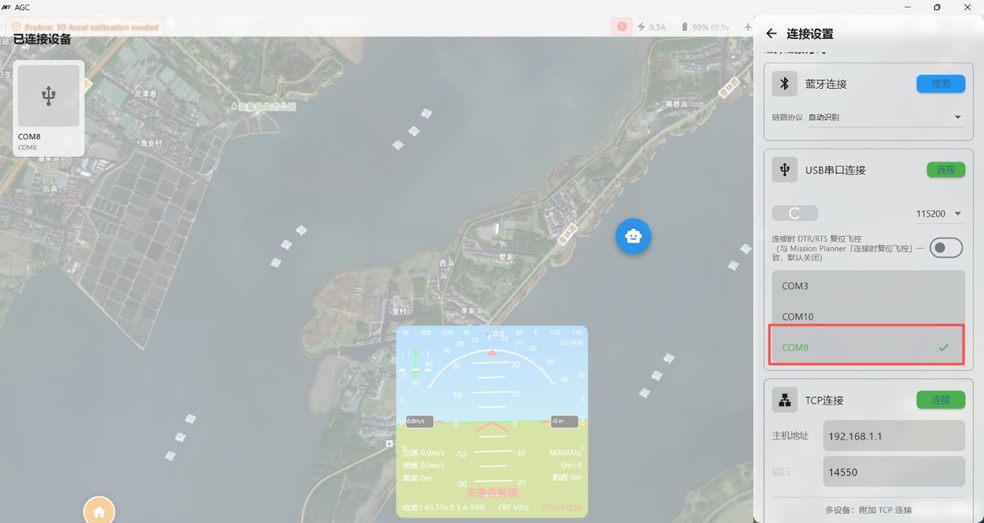 Click Connect and wait several seconds while the software reads data from the flight controller.
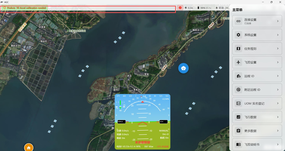
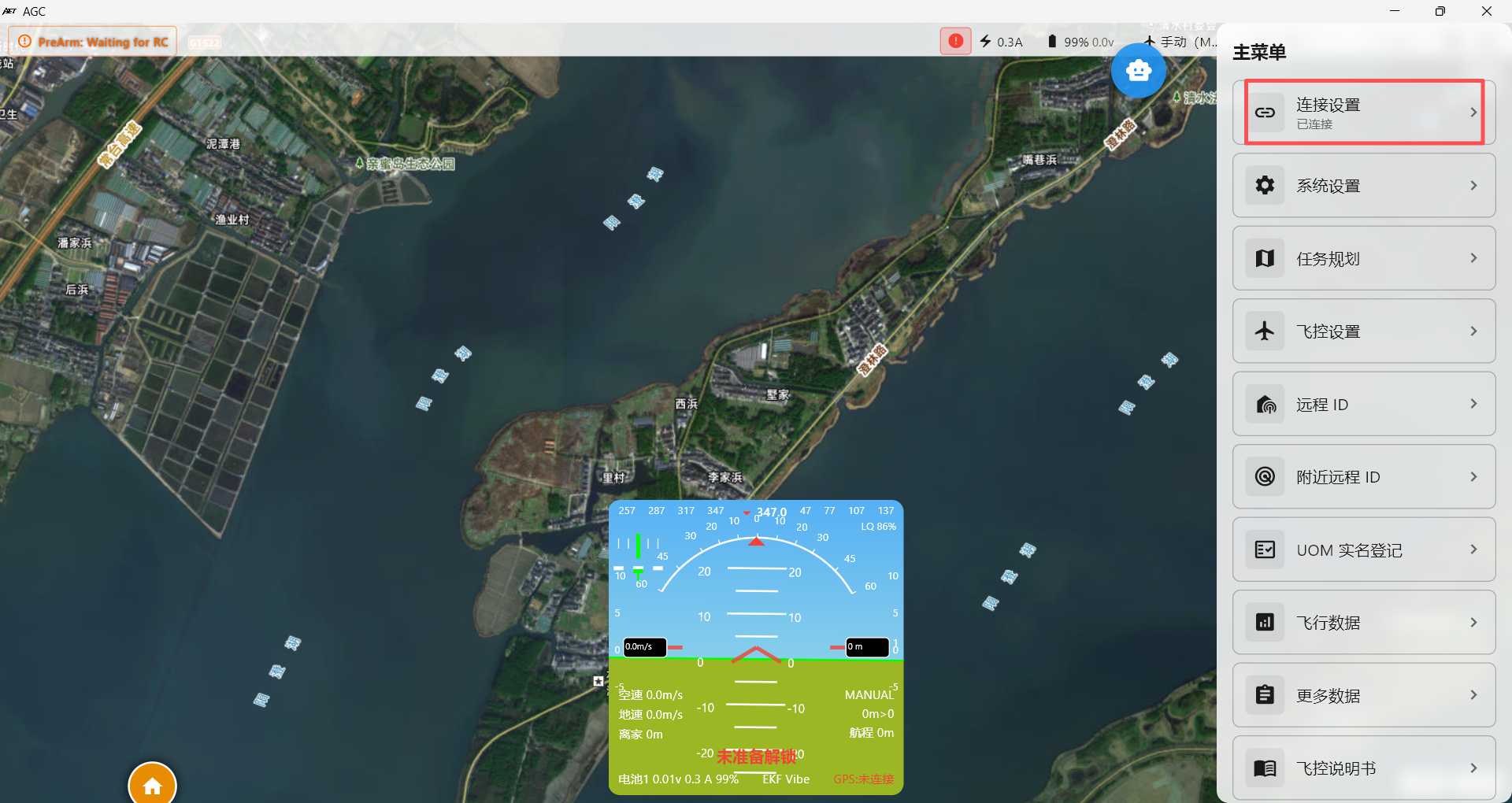
Connection successful.
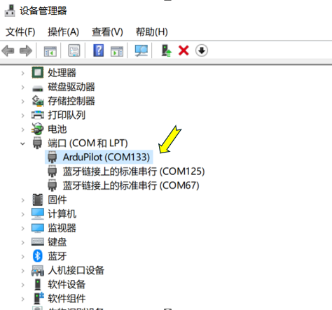
If the flight controller does not appear in the port drop-down menu after USB is connected, verify that the computer has recognized the flight controller driver and assigned a port. Check the Ports section in Windows Device Manager. If no port number is assigned, install the appropriate driver.
 The image below provides an overview of the first configuration and tuning page.
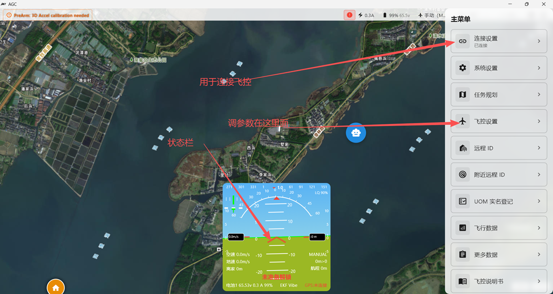
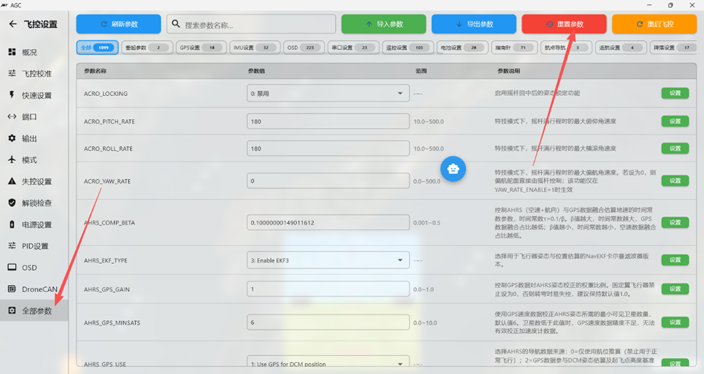
After flashing new firmware, we strongly recommend performing “Reset to Default Parameters” once before configuration.!!!!
Navigate to Flight Controller Settings → “Full Parameter List” → “Reset to Default Parameters.”
Section 2: Accelerometer and Level Calibration
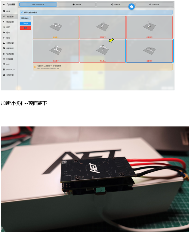
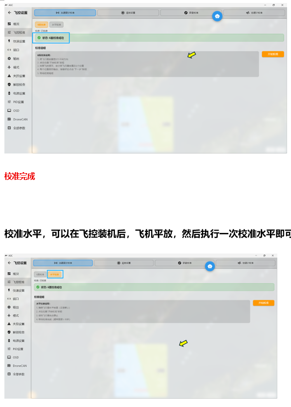
Click Initial Setup, then Accelerometer Calibration.
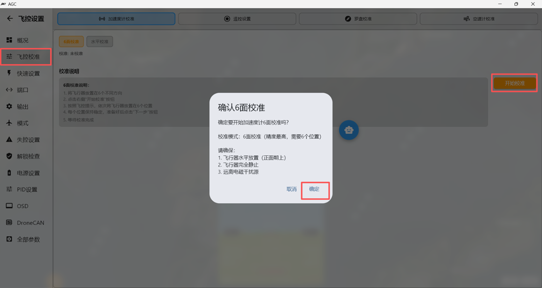
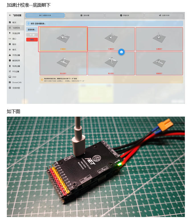
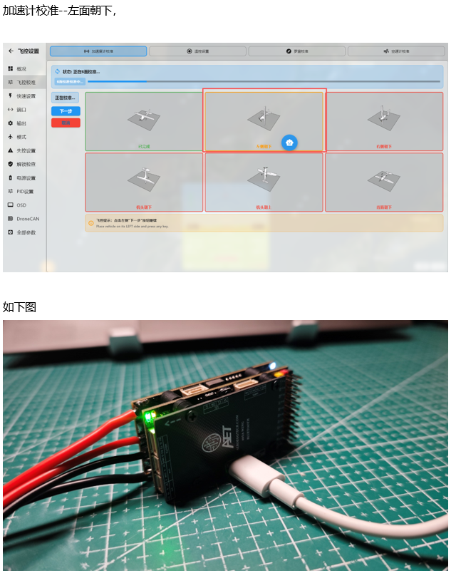
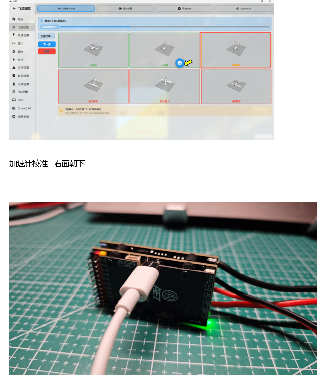
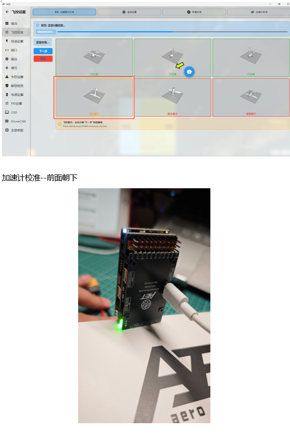
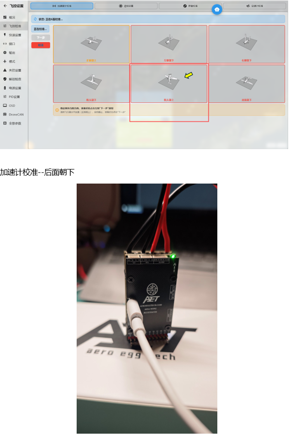
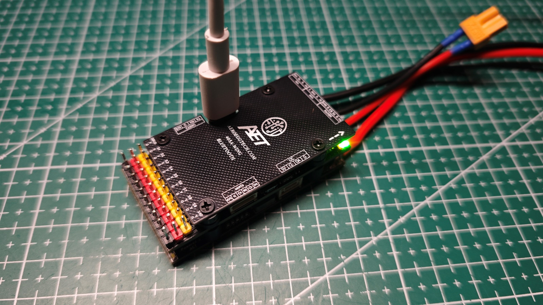
Click Calibrate Accelerometer. Follow the software prompts and place the flight controller on each of its six sides to complete six-position calibration, as shown below.
Section 3: Compass Setup。
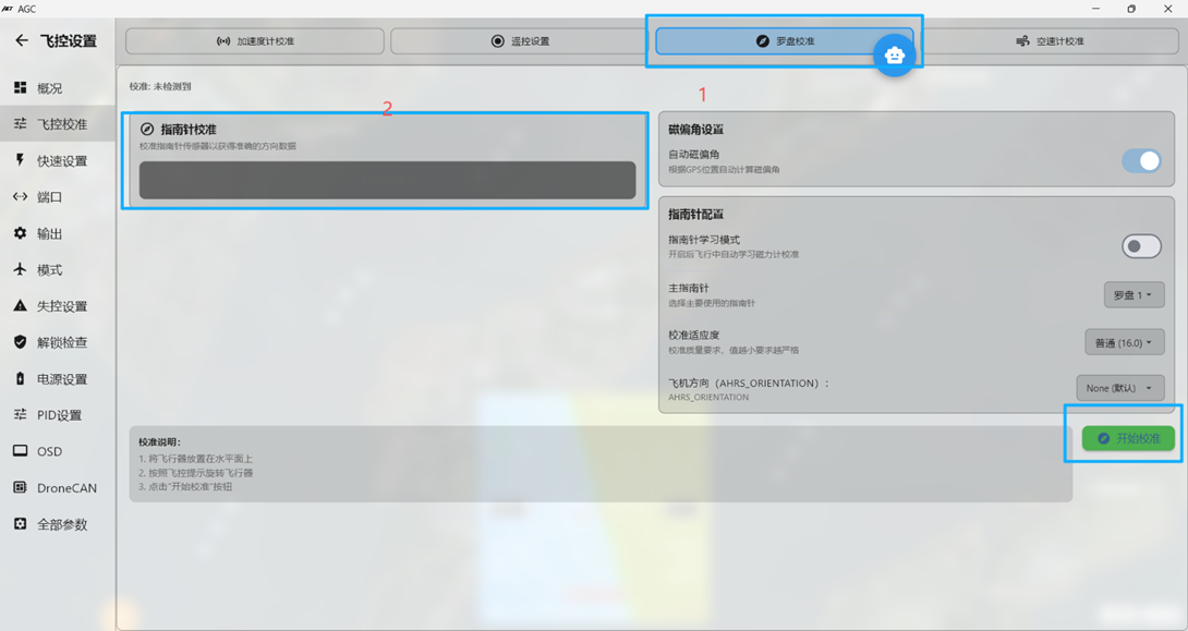
A compass (electronic compass) is not required for basic fixed-wing operation. The demonstration does not use a compass. After calibration, power off and restart the flight controller.
Section 4: Custom Servo and ESC Output Configuration
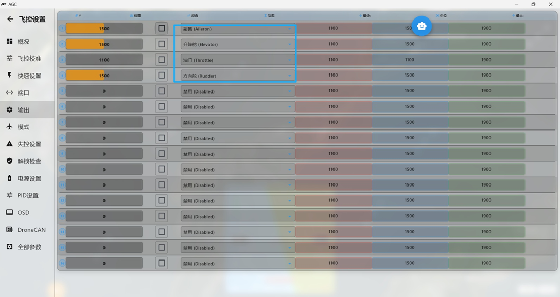 Ardupilot firmware supports fully customizable assignments for flight controller outputs S1–S10.
In the image above, #1 corresponds to flight controller S1, #2 corresponds to S2, and so on. 。 The default parameters use the conventional AETR layout shown above.
Aileron: aileron servo for roll control
Elevator: elevator servo for pitch control
Throttle: ESC throttle signal
Rudder: rudder servo for yaw control
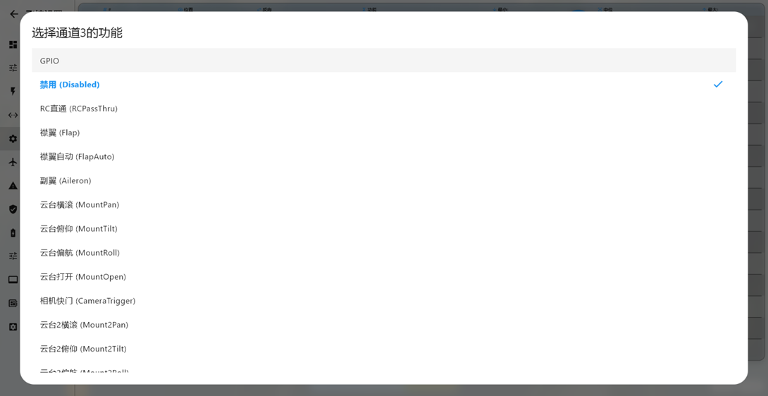
Each output channel can be assigned from its corresponding drop-down menu. This flexibility is one of the key features of Ardupilot firmware. After changing a custom output assignment, restart the flight controller for the change to take effect.
Common assignment types include:
Aileron: aileron servo for roll control
Elevator: elevator servo for pitch control
Throttle: ESC throttle signal
Rudder: rudder servo for yaw control
ElevonLeft: left flying-wing servo (combined aileron/elevator control)
ElevonRight: right flying-wing servo (combined aileron/elevator control)
ThrottleLeft: left motor ESC throttle signal for differential thrust
ThrottleRight: right motor ESC throttle signal for differential thrust
VTailLeft: left V-tail servo (combined elevator/rudder control)
VTailRight: right V-tail servo (combined elevator/rudder control)
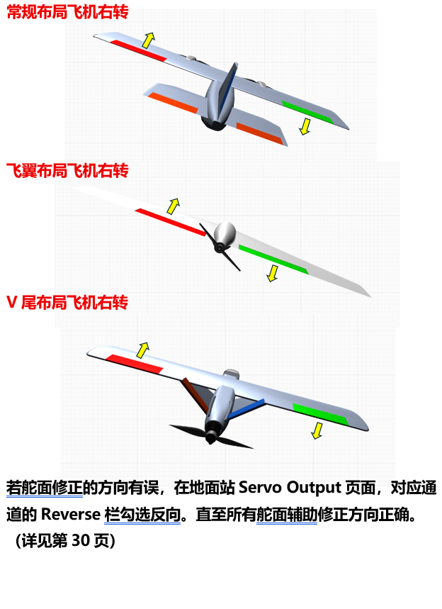
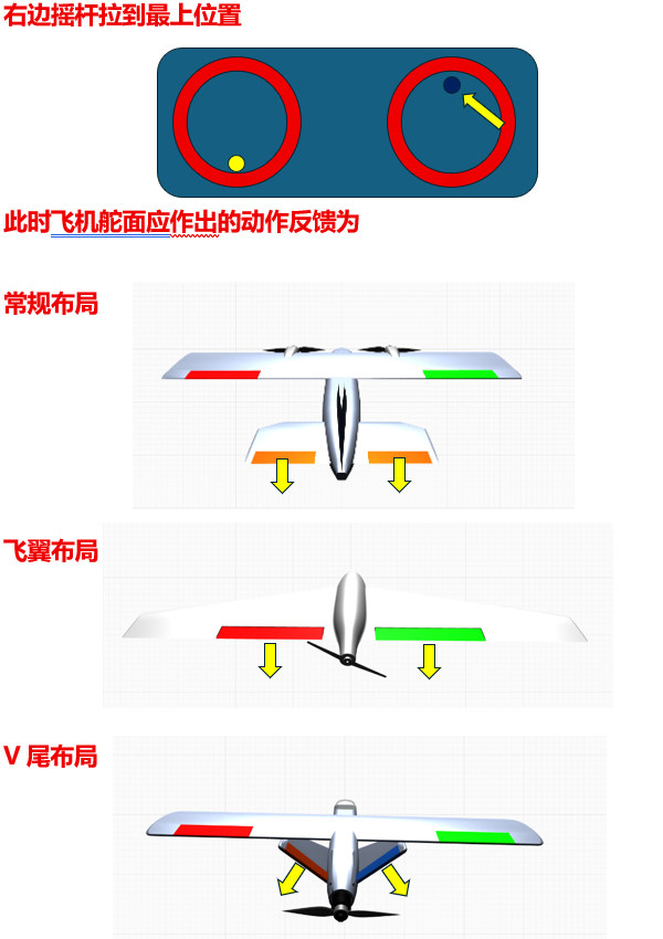
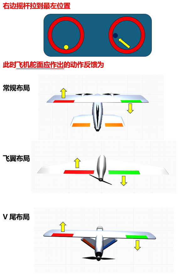
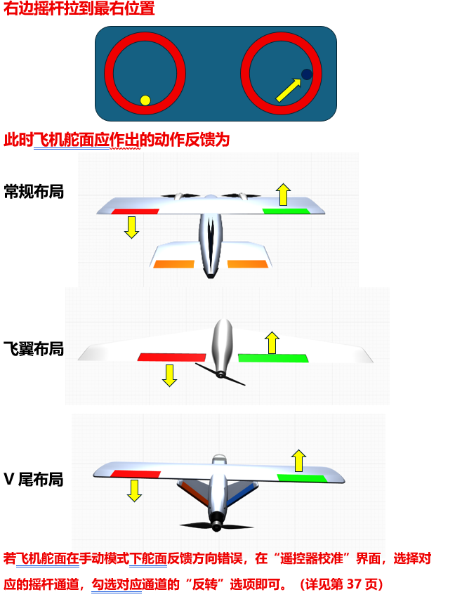
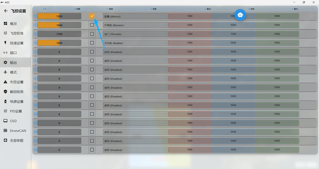 Ardupilot channel outputs update in real time. During later stabilization checks, if a channel moves in the wrong direction when the flight controller corrects aircraft attitude, select “Reverse” for that channel to invert its output.
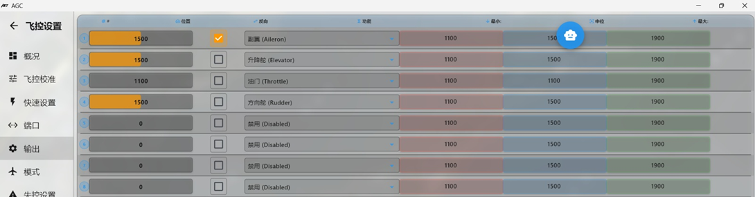
Example 1: For a single-motor pusher flying wing such as ARWING or Freewing, connect the left elevon servo to S1 and set #1 to ElevonLeft. If the servo moves in the wrong direction during setup, select Reverse for #1. Connect the ESC signal wire to S3 and set #3 to Throttle.
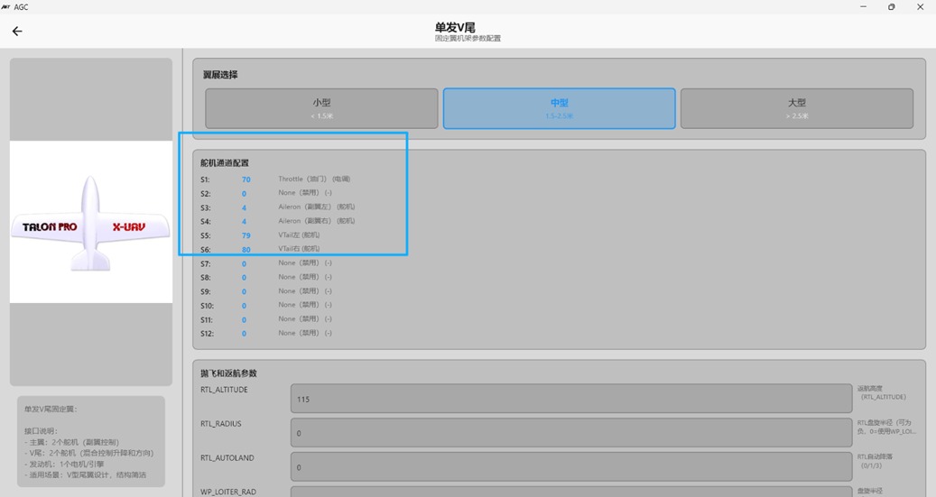
Example 2: For a single-motor 3D-printed V-tail aircraft, connect the motor to S1, the aileron servos to S3 and S4, the left V-tail servo to S5, and the right V-tail servo to S6.
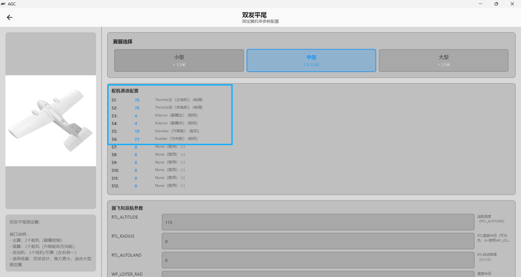
Example 3: For a twin-motor conventional-layout aircraft such as the Great White Shark (Fatty) without differential thrust, connect the two aileron servos to S3 and S4, and set both #3 and #4 to Aileron. Connect the two wing ESC signals to S1 and S2 in either order, and set #1 and #2 to Throttle. Connect the horizontal-tail elevator servo to S5 and set #5 to Elevator. Connect the vertical-tail rudder servo to S6 and set #6 to Rudder.
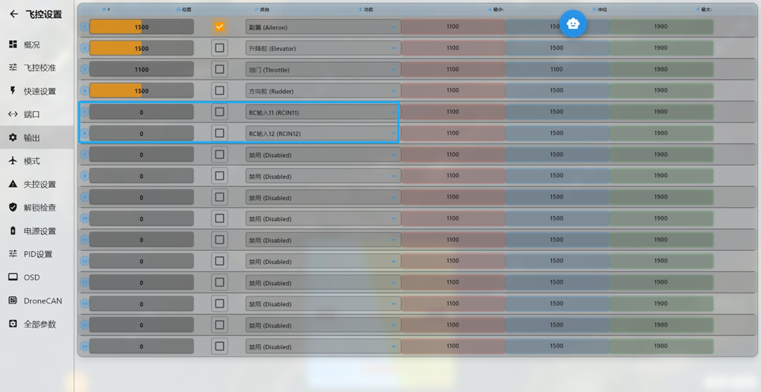
Example 4: To connect a servo gimbal to flight controller S5 and S6 for controlling the FPV camera viewing direction, and control it with custom radio transmitter knob channels 10 and 11, set #5 and #6 to RCIN10 and RCIN11.
Section 5: Flight Controller Serial-Port Definitions
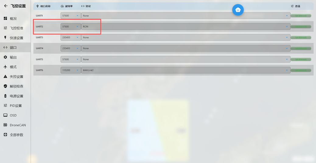
Define each serial-bus peripheral connected to the flight controller. The default flight controller parameters are shown above. The first column identifies the serial port; for example, PORT2 means serial port 2 (UART2). The next column specifies the baud rate for the corresponding interface.
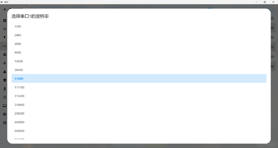
The Protocol column defines the interface type. Configure the baud rate and protocol according to the serial peripheral connected to each port.
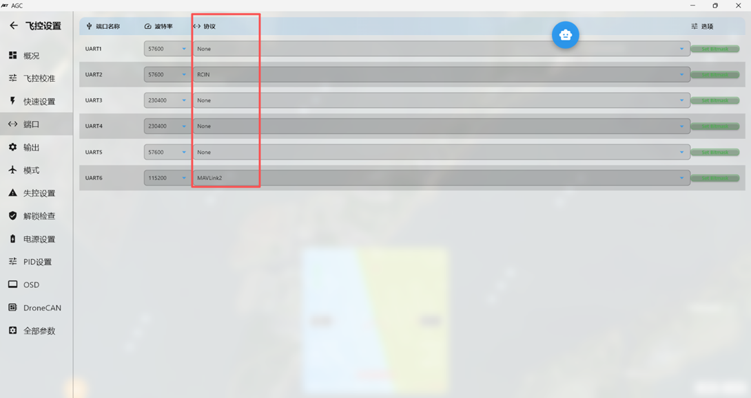
Receiver Setup: For an SBUS receiver, such as WFLY WBUS, RadioLink series, or Futaba series receivers, connect a 2.54 mm 3-pin Dupont plug directly to the flight controller SBUS port. The SBUS port corresponds to SERIAL PORT2 (UART2). With the default flight controller setting of 57600 RCIN, the SBUS receiver signal is detected automatically.
For an ELRS/CRSF receiver, use an SH1.0 4P connector and connect it to the UART2 interface on the side of the flight controller. See page 10 of this guide for the wiring diagram. These receivers generally use 115200 RCIN. The flight controller firmware no longer supports PPM or PWM receivers.
GPS Module Setup:
Use an SH1.0 6P connector to connect the GPS to the UART5 interface on the side of the flight controller. See page 11 of this guide for the wiring diagram. Most GPS modules use 38400 GPS. Some GPS modules support a Speed baud rate of up to 115200.
Digital Video Air Unit Setup:
Use an SH1.0 6P connector to connect the digital video air unit to the HDVTX interface on the front of the flight controller, which corresponds to UART3. See page 12 of this guide for the wiring diagram. Digital video air units generally use 115200 DispiayPort.
This includes DJI air units compatible with DJI G2, G3, and N3 goggles; Caddx Avatar series air units; and the open-source OpenIPC HD video system. For older DJI air units and Vista used with DJI V1 or V2 goggles, set the UART3 Protcol value to DJI FPV.
Onboard Flight Controller Bluetooth Telemetry Module Setup
The onboard Bluetooth telemetry module on the AET F405A WING flight controller maps directly to UART6.
Set this interface to 115200 Mavlink2.
External Telemetry Module Setup
Connect an external telemetry module to the TX1 and RX1 solder pads on the rear of the flight controller. These pads correspond to UART1.
Common telemetry links generally use 115200 Mavlink2.
Recommended settings for common peripheral interfaces are shown below.
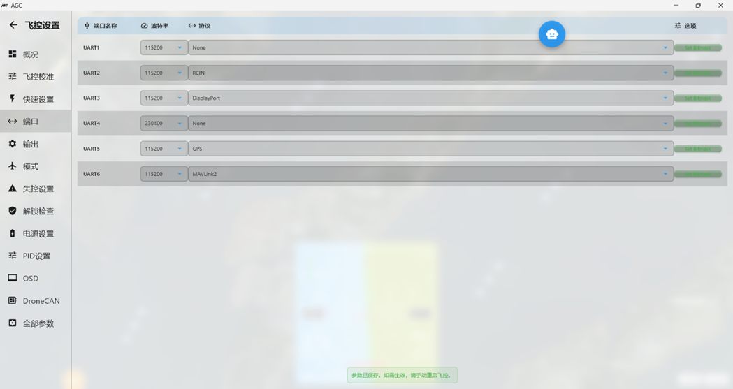
Connect the ELRS receiver to UART2.
Connect the digital HD video air unit to UART3.
Connect the GPS module to UART5.
Reserve UART6 for the onboard flight controller Bluetooth telemetry module.
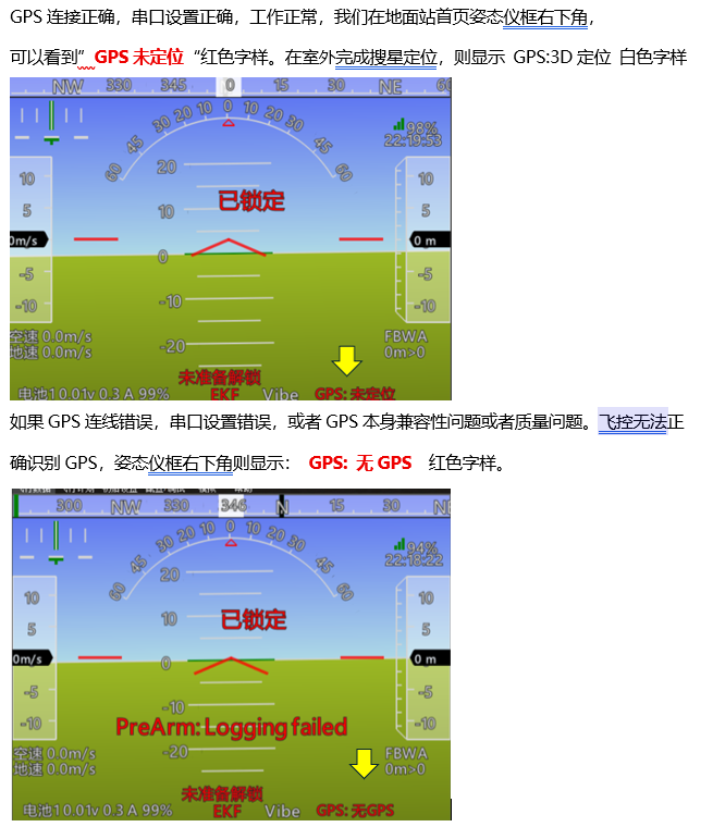
After configuring all serial peripherals and verifying the wiring, the receiver and GPS module should be connected and configured correctly. Use the following steps to verify that radio transmitter signals reach the flight controller through the receiver and that the GPS module operates correctly.
Section 6: Radio Transmitter Calibration
If the radio transmitter is powered on and paired with the receiver, but the receiver wiring or serial-port configuration is incorrect, the Radio Calibration page will not show the Thrttle signal or channel values for channels 5–16, as shown below.
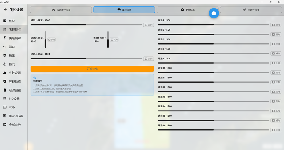
When the receiver wiring and corresponding serial-port settings are correct, black slider indicators appear for all channels.
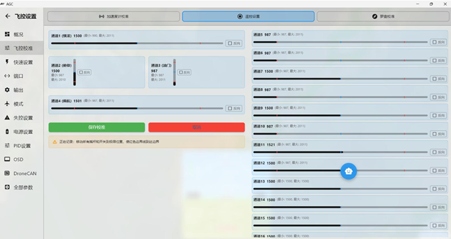
You can now calibrate the radio transmitter sticks and other switch channels.
Click “Calibrate Radio” to begin calibration.
Move all sticks through their full ranges and operate every switch channel, including the six-position switch, through all positions. Red markers on the screen record each channel’s minimum and maximum output values.
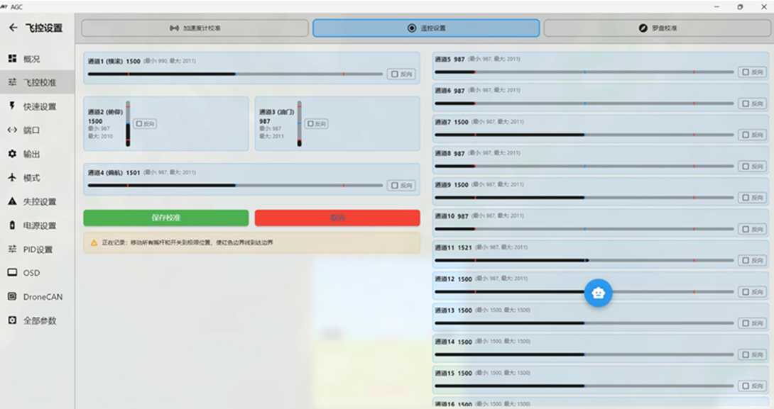
Radio transmitter calibration is now complete.
Section 7: Verify the GPS Module Connection
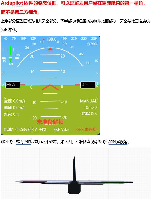
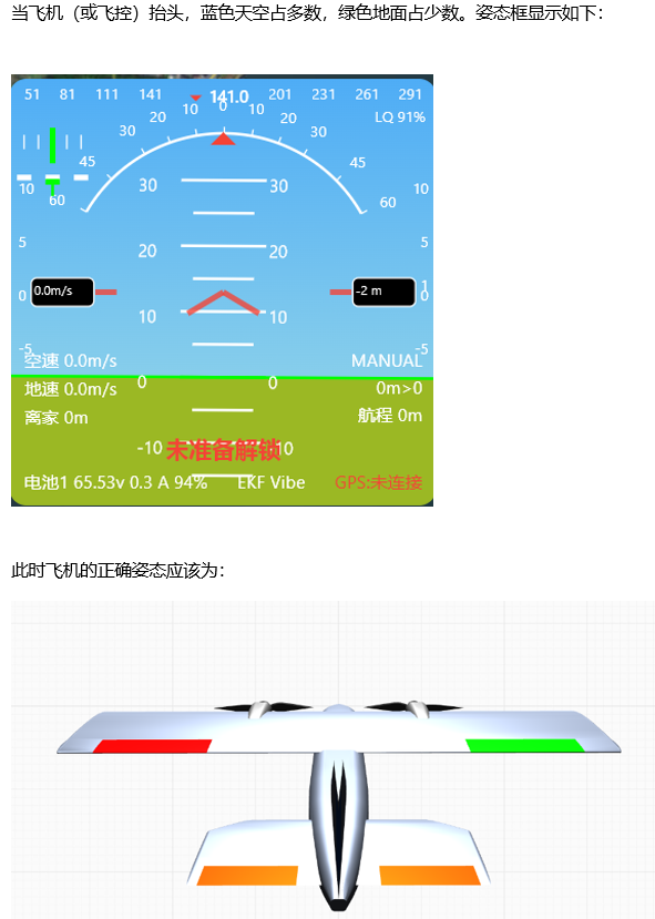
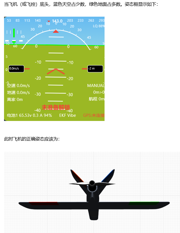
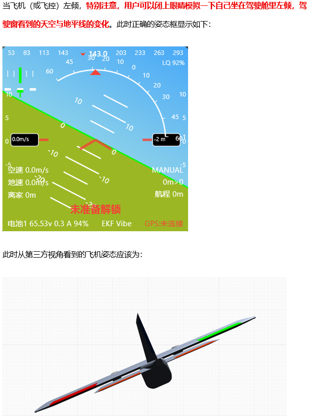
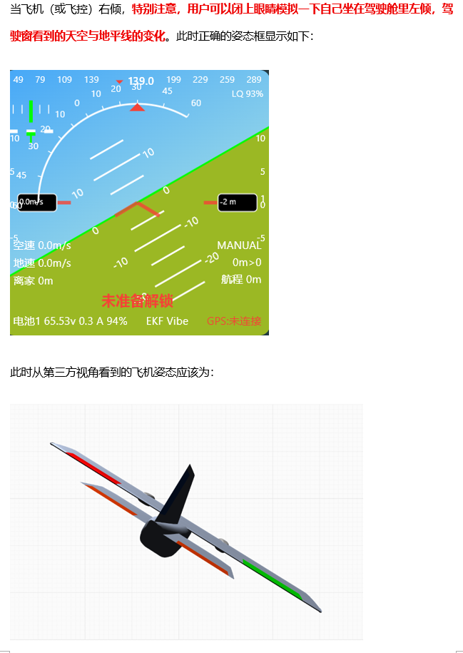
Section 8: Verify Flight Controller Orientation and Attitude Display
Section 9: Flight Mode Setup
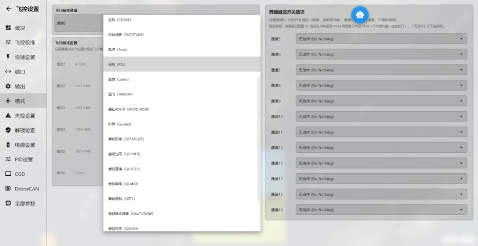
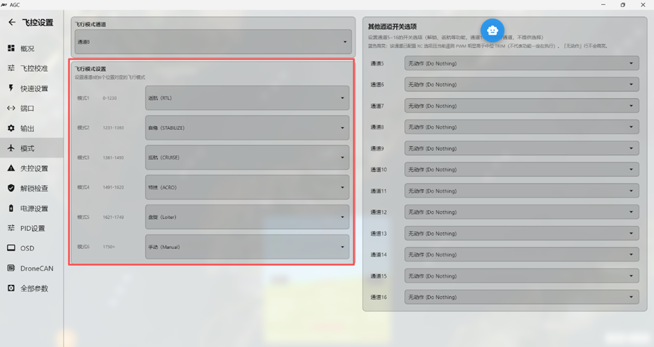
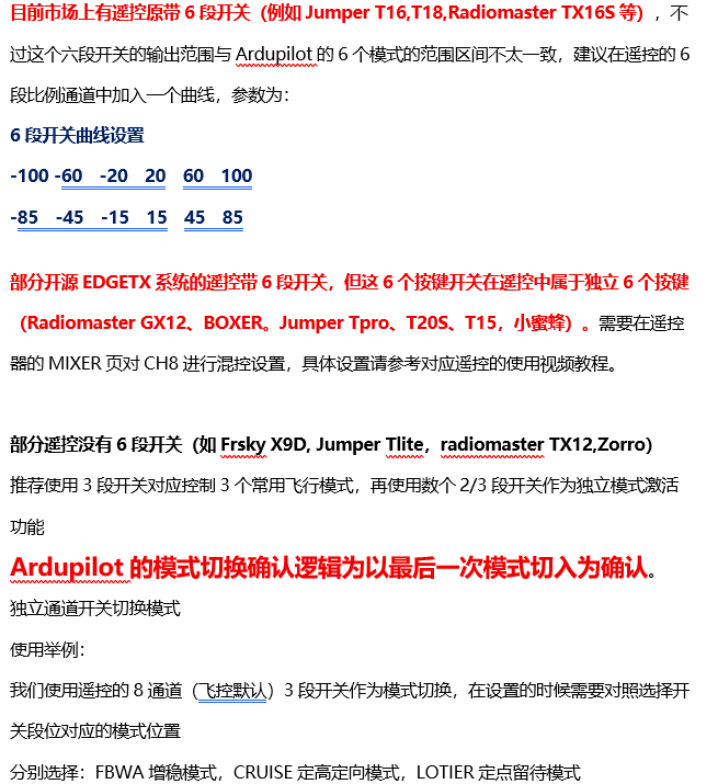
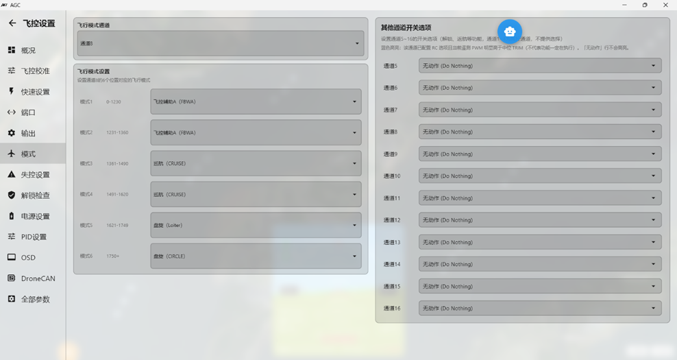
Ardupilot uses one proportional channel to select among six flight modes. By default, this is radio transmitter channel 8. The image below shows the default preset values for the mode-selection channel.
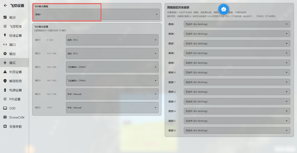
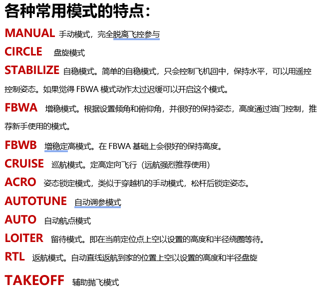
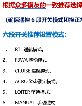
Use the drop-down arrow to the right of each flight mode to select the required commonly used flight mode.