Chapter 5: Channel Configuration, Servo Setup and Inspection, and ESC Calibration
5. Output Setup
5.1 Channel Configuration
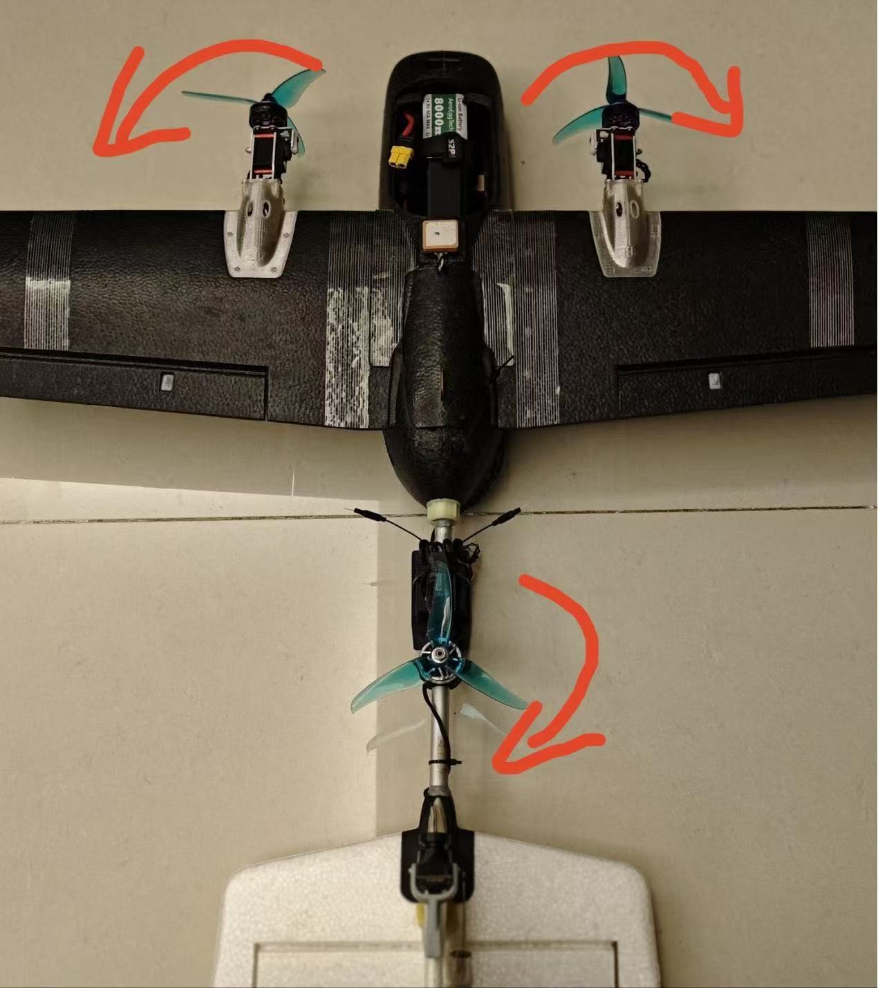
Open SERVO OUTPUT to configure each flight controller output channel. AP firmware uses the multicopter Y-3 motor definition: the front-left motor is MOTOR2, the front-right motor is MOTOR1, and the rear motor is MOTOR4, as shown below. The rotation directions in the diagram do not need to be followed. Do not configure the motors as MOTO1\MOTOR2\MOTOR3.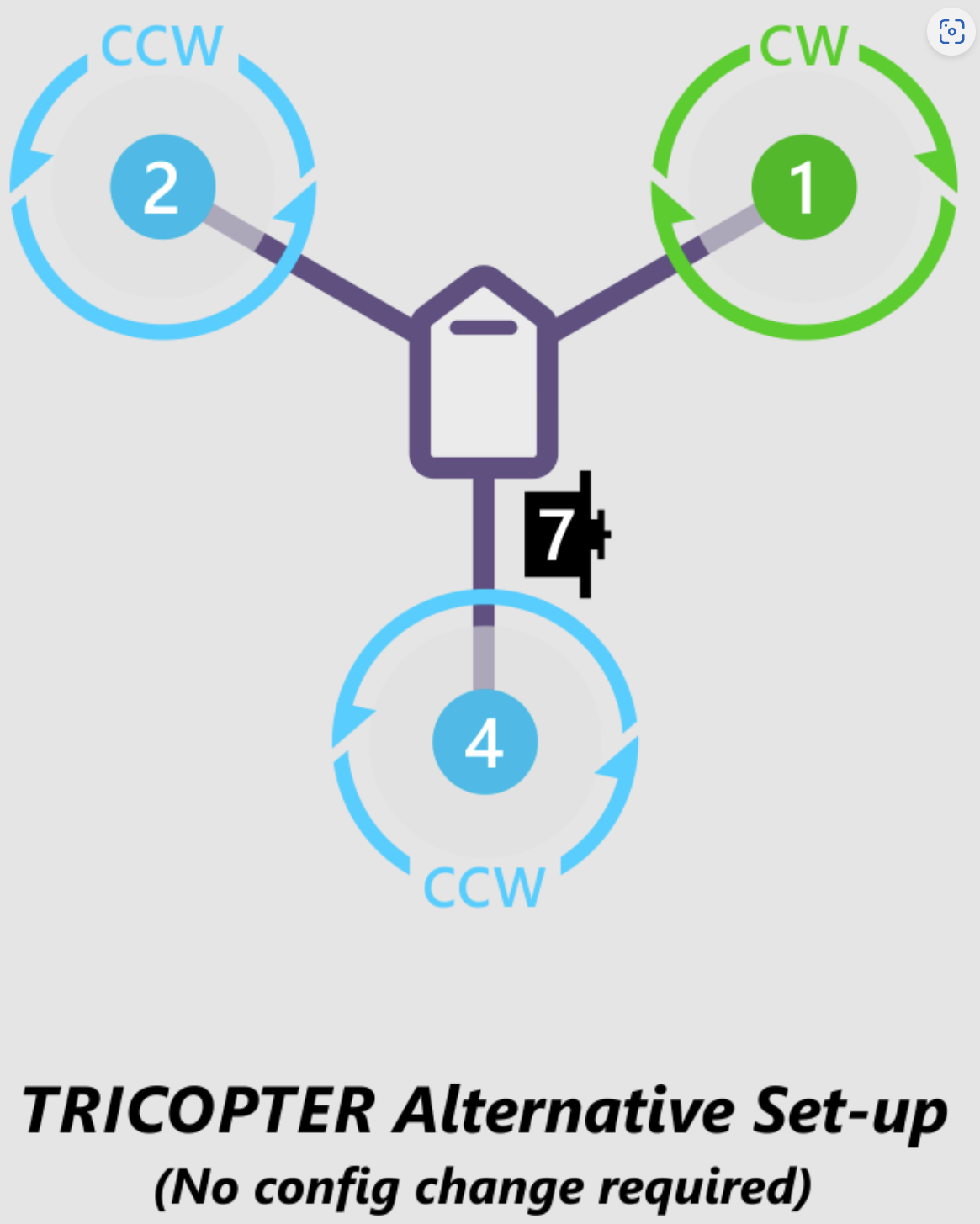
The following example uses the Cike T1 currently being configured, with the flight controller wiring shown below: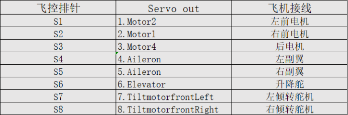
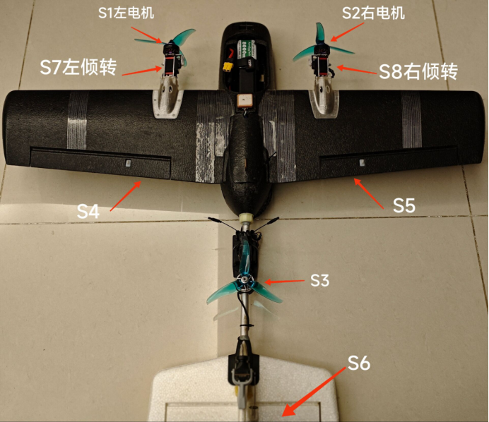
The flight controller includes a BEC. If the ESC also includes a BEC, remove the center voltage wire from the connector and insulate it securely to prevent movement during flight from allowing it to contact a conductor and cause a short circuit.
Assign the following channels to the aircraft control surfaces and throttle according to the wiring.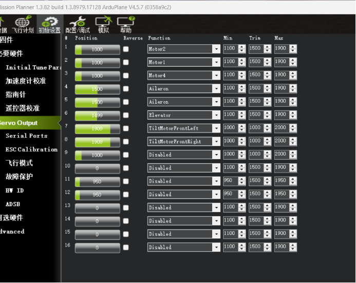
5.2 Servo and Control Surface Inspection
5.2.1 Tilt Servo Inspection
In Q_stabilize mode, both tilt servos should be vertical at 90°, as shown below.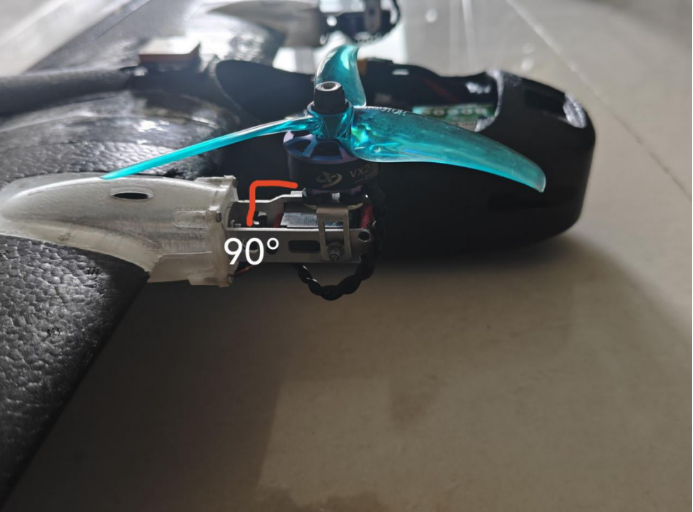
The ground station OUTPUT screen is shown below. In Q_stabilize mode, the left tilt servo PWM value is low and the right tilt servo PWM value is high.
Adjust this according to the actual installation. The left tilt servo PWM value is not necessarily low in multicopter mode on every aircraft.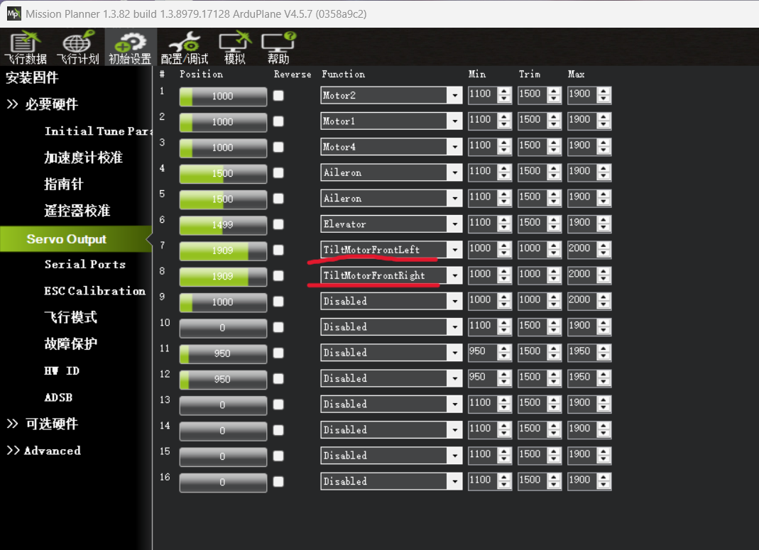
If one servo is vertical at 90° while the other is horizontal at 180°, select Reverse for the channel assigned to the incorrectly positioned servo. If both tilt servos are raised but are not exactly vertical, adjust the channel 7 min value and channel 8 max value until both servos are vertical.
Example:
If the left tilt servo is not vertical and is below 90°: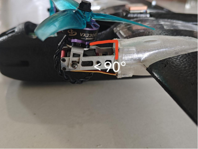
Increase the channel 7 min value until the servo is vertical. Conversely, if the left tilt servo is above 90°, decrease the channel 7 min value.
Similarly, if the right tilt servo is not vertical, adjust the channel 8 max value.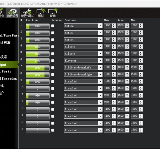
In FBWA mode, both tilt servos should be horizontal at 180°, as shown below.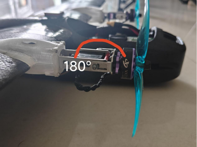
The ground station OUTPUT display is shown below. In FBWA mode, the left tilt servo PWM value is high and the right tilt servo PWM value is low. The adjustment method is the same as for correcting nonvertical tilt servos in Q_stabilize mode. In FBWA mode, adjust the maximum value for the left tilt servo on channel 7 and the minimum value for the right tilt servo on channel 8.
Example:
If the left tilt servo is below 180°: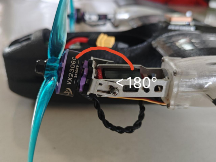
Increase the channel 7 max value. Conversely, if the left tilt servo is above 180°, decrease the channel 7 max value.
Similarly, if the right tilt servo is not horizontal, adjust the channel 8 min value.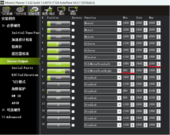
In summary, the servo position or angle can be controlled precisely by adjusting the minimum and maximum PWM values for each mode. Use the MP ground station output screen to observe and optimize these settings.
When adjusting min and max values, the ground station may display an out-of-range warning. Click Confirm to continue.
5.2.2 Fixed-Wing Control Surface Inspection
For details, see the AP Quick Configuration and Tuning Guide:
https://doc.aeroeggtech.com/en/books/aet-h743-basic-ardupilot/page/aet-h743-ardupilot
(1) Use the radio transmitter to switch to FBWA mode. Move the pitch, roll, and yaw controls and verify that the aircraft control surfaces respond correctly. If a control surface moves in the wrong direction, find the corresponding channel on the SERVO OUTPUT screen and select REVERSE.
(2) Check the direction of automatic control-surface correction by positioning the aircraft to simulate different flight attitudes. For example, lower the nose and verify that the elevator moves to command nose-up correction and restore level flight. Perform equivalent checks for roll and yaw.
This check verifies that the flight controller output and servo response are consistent. If the control-surface response is still incorrect, return to Section 2.1, Radio Transmitter Calibration, and repeat the checks. Also verify the servo wiring.
5.3 ESC Calibration
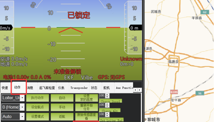
Open the Flight Data screen, locate the Actions panel, and click Arm.
a. Confirm that the radio transmitter has been calibrated. Switch the radio transmitter to Q_stabilize mode and move the throttle to maximum.
b. Click Force Arm to force arming. Do not install propellers during this test.
c. Connect battery power to the flight controller. After the ESC emits two beeps, move the throttle to minimum.
d. ESC calibration is complete. Increase the throttle slightly and verify that each motor rotation direction matches its propeller. If a motor rotates in the wrong direction, swap any two of that motor’s ESC phase wires to reverse it.