Chapter 9: Connecting, Configuring, and Using the Airspeed Sensor
This example uses a Fapple airspeed sensor with the MS4525D protocol.
Recommended wiring: use the 5V, GND, SCL, and SDA pins on the side uart4 connector.
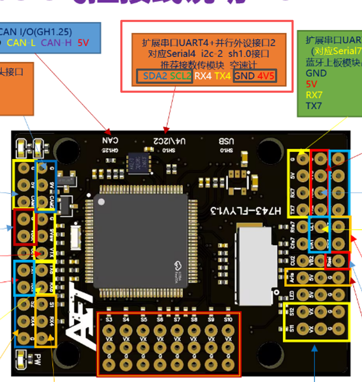
Install the airspeed sensor on the airframe according to its installation instructions, minimizing the effect of airframe turbulence on the sensor.
Connect the airspeed sensor 5V and GND pins to the flight controller 5V and GND pins to ensure proper power. Connect the sensor SDA and SCL pins to the flight controller SDA and SCL pins.
Search for and set the following parameters in the full parameter list:
ARSPD_TYPE 1
ARSPD_OPTION 15
ARSPD_AUTOCAL 1
ARSPD_SKIPCAL 1
On the OSD layout page, enable ASPD1, drag it to the desired position, and write the settings.
Checking Airspeed Sensor Operation
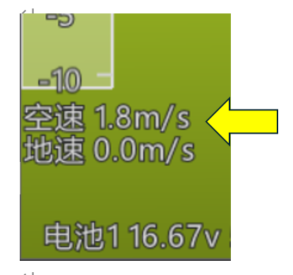
When the airspeed sensor is correctly connected to the flight controller, its status is visible in the ground station as shown below.
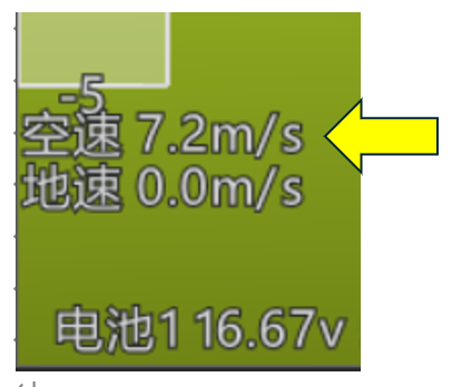
Blow into the airspeed sensor dynamic-pressure port, or point it into airflow from a fan. Confirm that the airspeed value changes in the ground station, as shown below.
A basic calibration is required on the first flight. After takeoff, switch to LOITER mode and allow the aircraft to circle at its current altitude for 5~10 minutes so the flight controller can automatically calibrate the airspeed sensor. After the aircraft lands normally, connect the ground station and disable automatic calibration by setting: ARSPD_AUTOCAL 2
The airspeed sensor configuration is now complete.
For additional settings, refer to the parameters specified by the airspeed sensor manufacturer.