Chapter 3: Basic Configuration and Tuning
Section 1: Connect the Ground Station and Reset Default Parameters. Open the MissionPlanner configuration and tuning software.
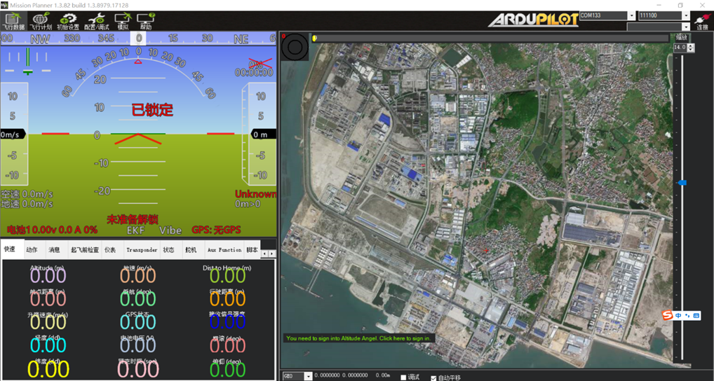 If the live satellite map cannot be loaded, open the Flight Plan page in the ground station and select a map source on the right. AMap Satellite Map is generally recommended. After selecting it, close the ground station and relaunch MissionPlanner. The ground station will then load AMap Satellite Map online.
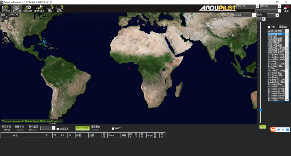
Connect the flight controller to the computer with a Type-C data cable. In the upper-right corner of MP, select the port assigned to the flight controller, as shown below:
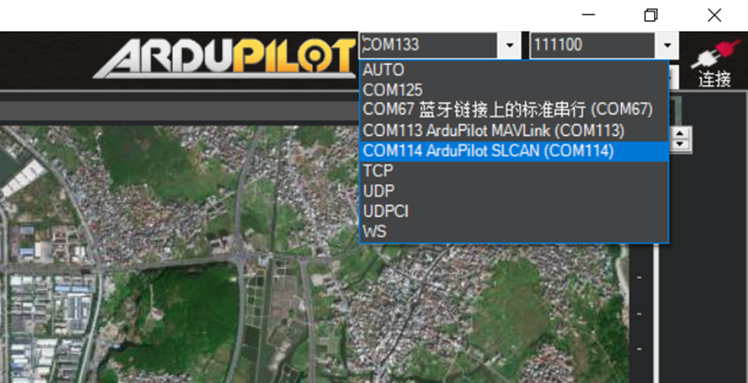 Click Connect and wait a few seconds while the software reads data from the flight controller.
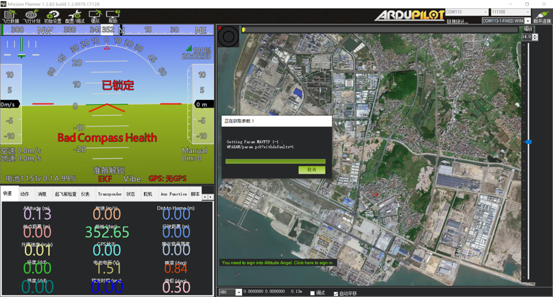 Connected successfully.
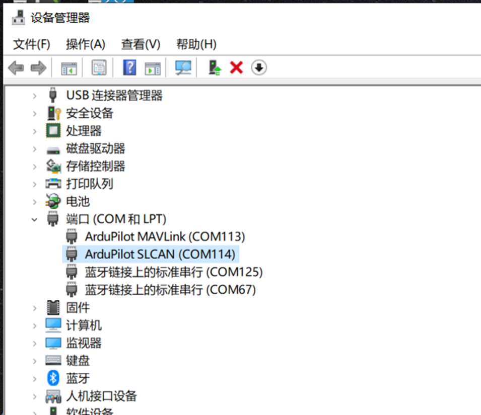
If the flight controller does not appear in the port drop-down list after USB is connected, verify that the computer has correctly recognized the flight controller driver and assigned a port. Check the Ports section in Windows Device Manager. If no port number is assigned, install the appropriate driver.
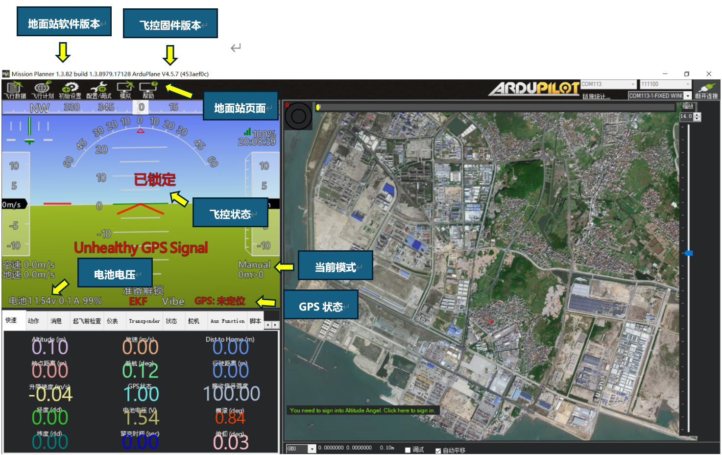
The following image provides an overview of the first configuration page.
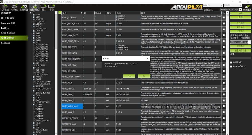
After flashing new firmware, it is strongly recommended to perform Reset to Default Parameters once.
Navigate to Config/Tuning -- Full Parameter List -- Reset to Default Parameters.
Click once. When the ground station requests confirmation, click Yes.
Section 2: Accelerometer Calibration and Level Calibration
Open Initial Setup, then Accelerometer Calibration.
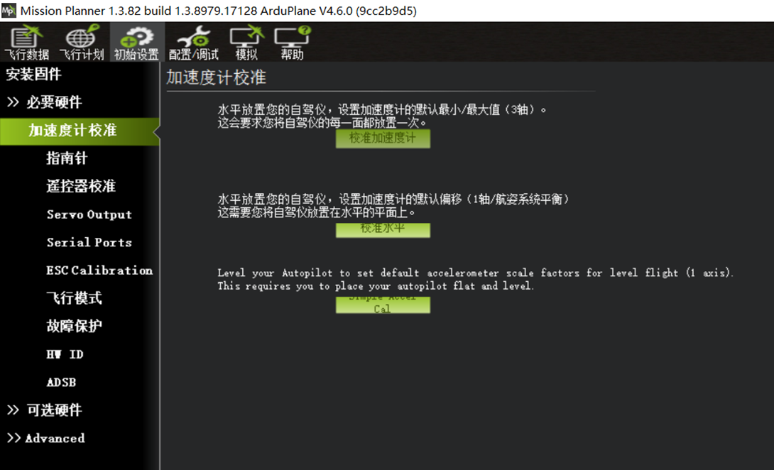
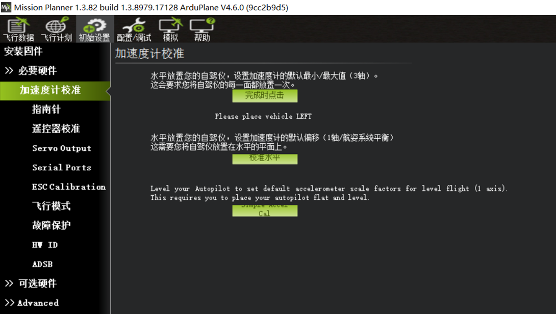 Click Calibrate Accel. Follow the software prompts to place the flight controller on each of its six faces and complete calibration, as shown below.
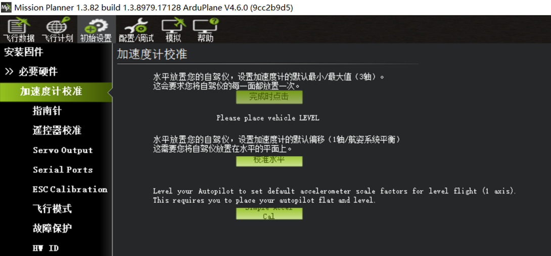 Please place vehicle LEVEL -- accelerometer calibration with the bottom face down, as shown below.
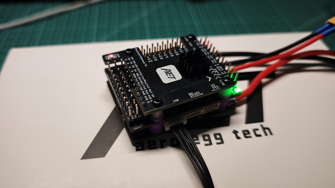 Please place vehicle LEFT -- accelerometer calibration with the left face down, as shown below.
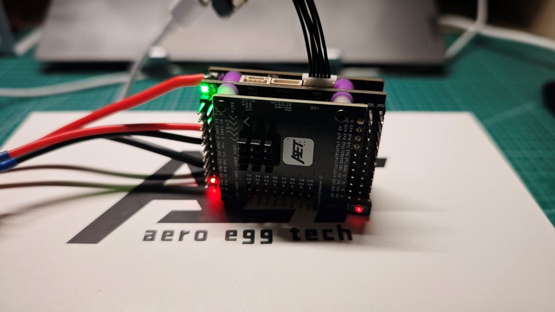
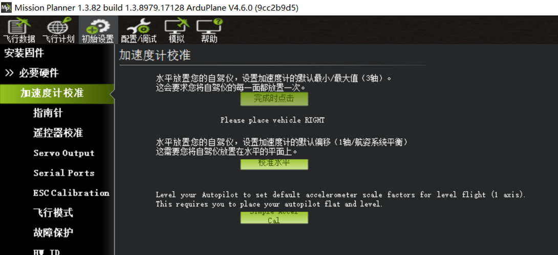 Please place vehicle RIGHT -- accelerometer calibration with the right face down.
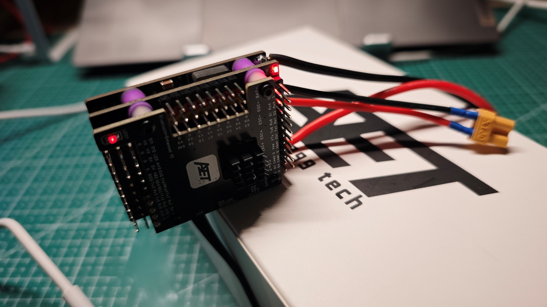
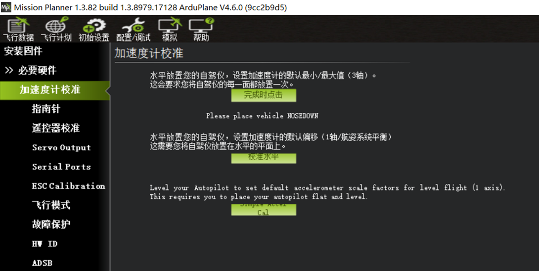 Please place vehicle NOSEDOWN -- accelerometer calibration with the front face down.
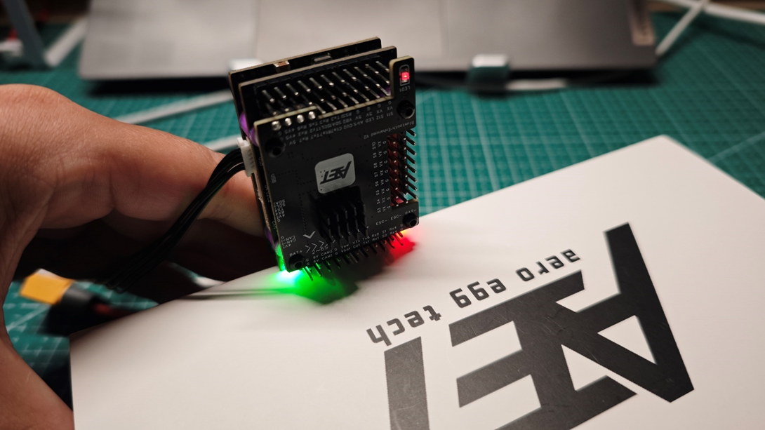
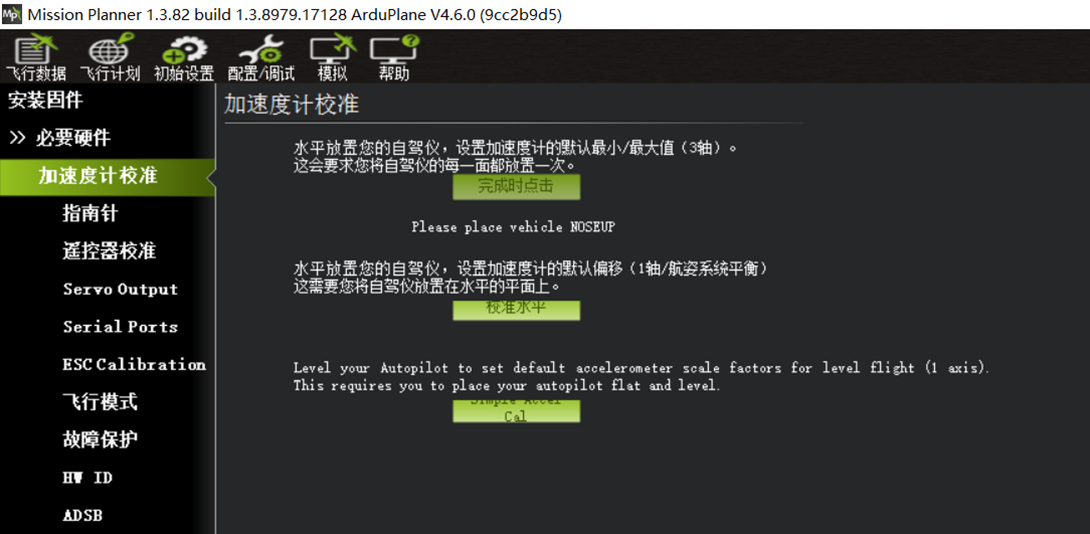 Please place vehicle NOSEUP -- accelerometer calibration with the rear face down.
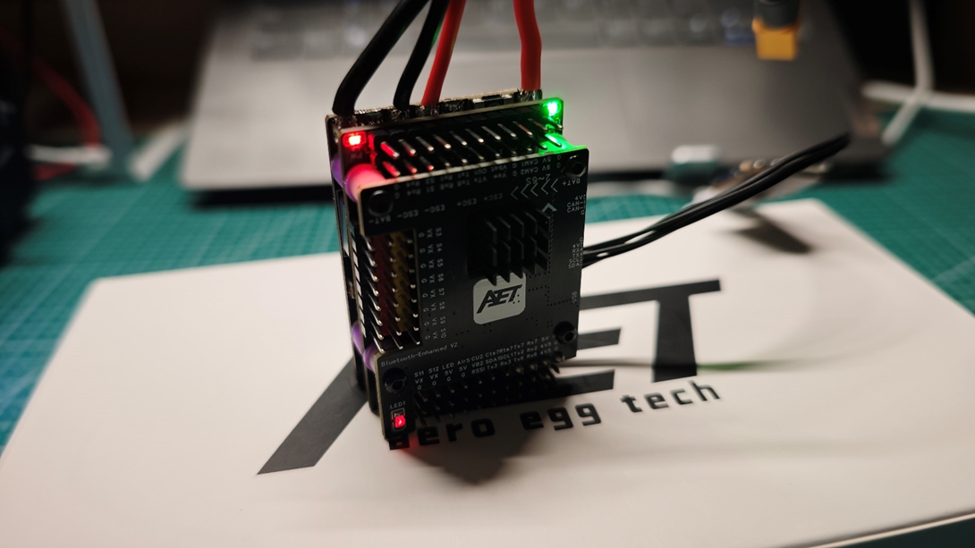
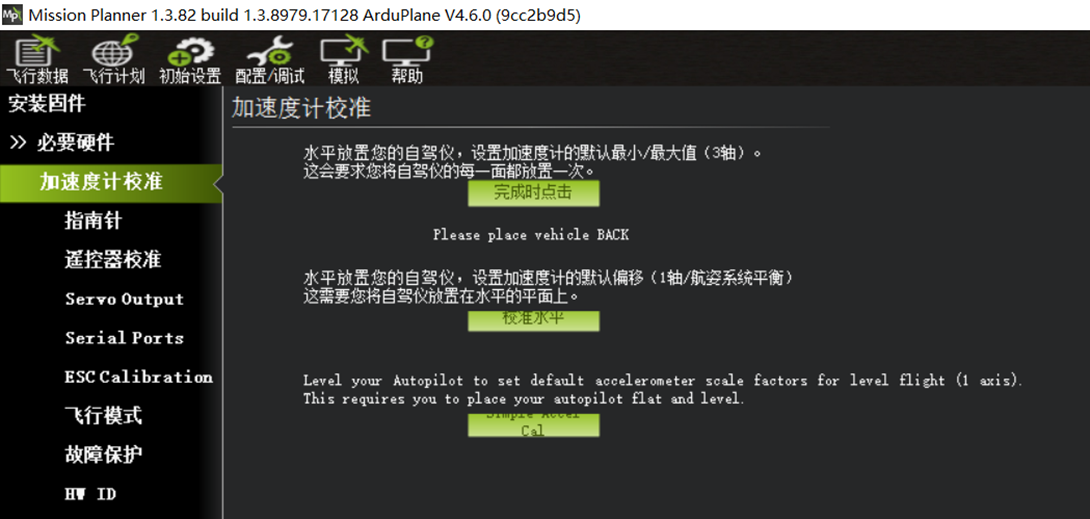 Please place vehicle BACK -- accelerometer calibration with the top face down.
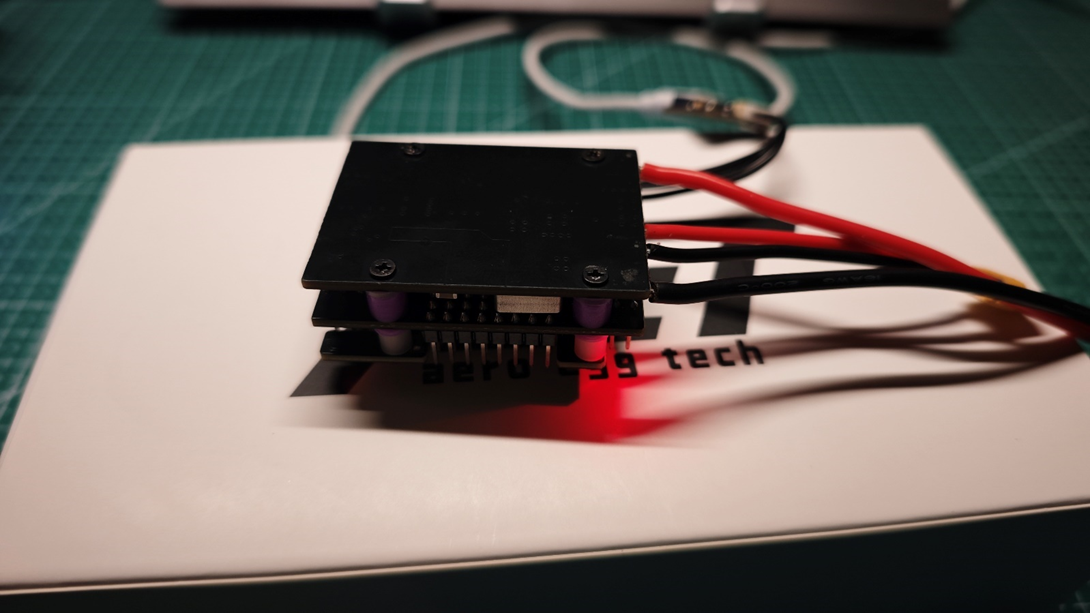
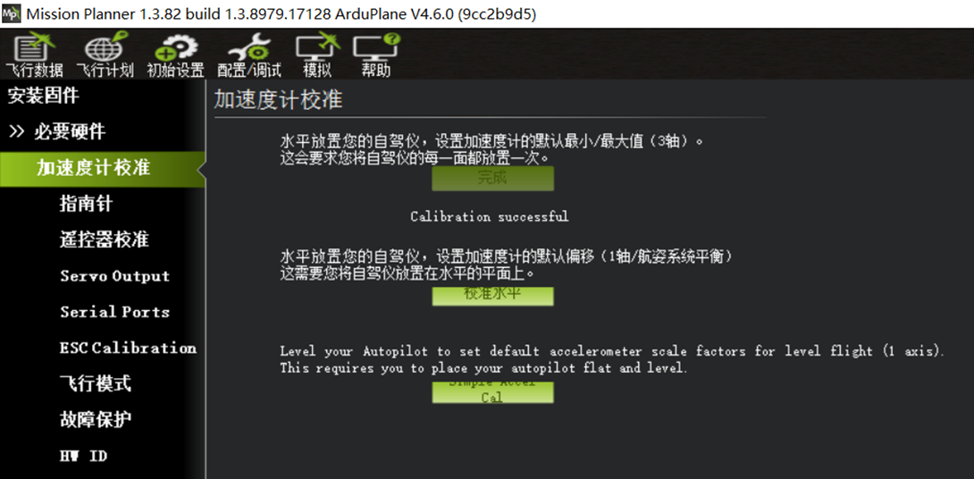 Calibration complete.
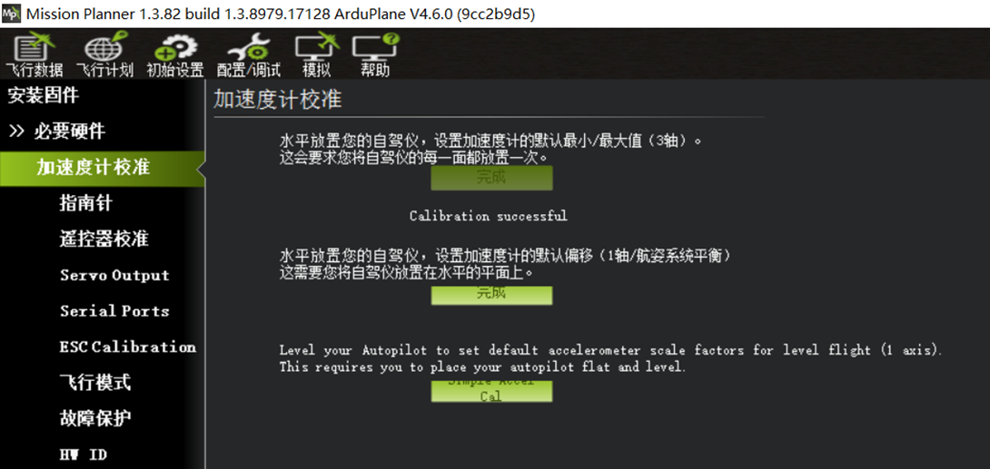
Level calibration can be performed after the flight controller is installed. Place the aircraft on a level surface and run Calibrate Level once.
Section 3: Compass Configuration
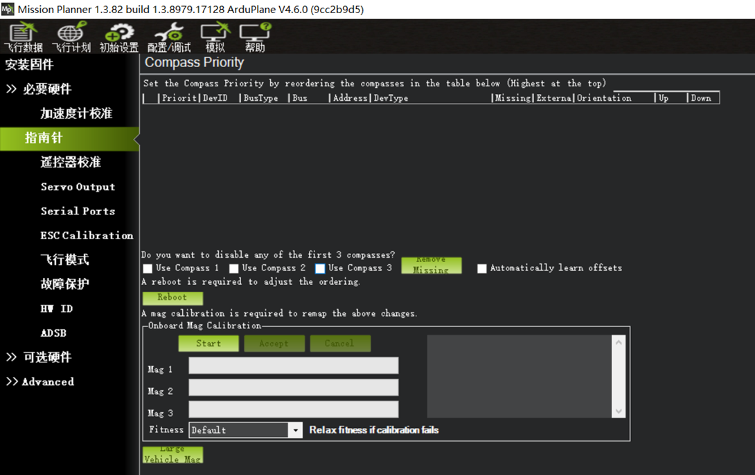 A compass (electronic compass) is not required for basic fixed-wing operation.
The compass options enabled by default on the flight controller can be disabled.
On the Initial Setup -- Compass page,
clear Use Compass1, Use Compass2, and Use Compass3.
Click Reboot to restart the flight controller.
Section 4: Custom Servo and ESC Output Configuration -- Servo Outputs
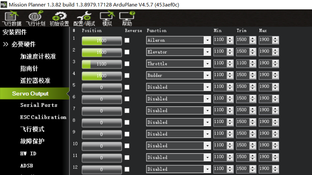
ArduPilot firmware supports fully customizable outputs on flight controller ports S1~S12.
In the image above, #1 corresponds to flight controller S1, #2 corresponds to S2, and so on.
The default configuration uses a conventional AETR layout, as shown above.
Aileron: roll-control aileron servo.
Elevator: pitch-control elevator servo.
Throttle: ESC throttle signal.
Rudder: yaw-control rudder servo.
S1 and S2 on this flight controller are not recommended for servos because they do not provide 5V servo power; they can be configured as ESC signal outputs.
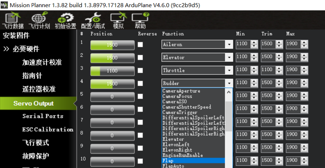
Each Servo output channel can be assigned from its corresponding drop-down menu. This is one of the key capabilities of ArduPilot firmware. Restart the flight controller after changing a custom Servo assignment.
Common output function assignments include:
Aileron: roll-control aileron servo.
Elevator: pitch-control elevator servo.
Throttle: ESC throttle signal.
Rudder: yaw-control rudder servo.
ElevonLeft left flying-wing servo (combined aileron/elevator control).
ElevonRight right flying-wing servo (combined aileron/elevator control).
ThrottleLeft left ESC throttle signal for differential thrust on a twin-motor aircraft.
ThrottleRight right ESC throttle signal for differential thrust on a twin-motor aircraft.
VTailLeft left V-tail servo (combined elevator/rudder control).
VTailRight right V-tail servo (combined elevator/rudder control).
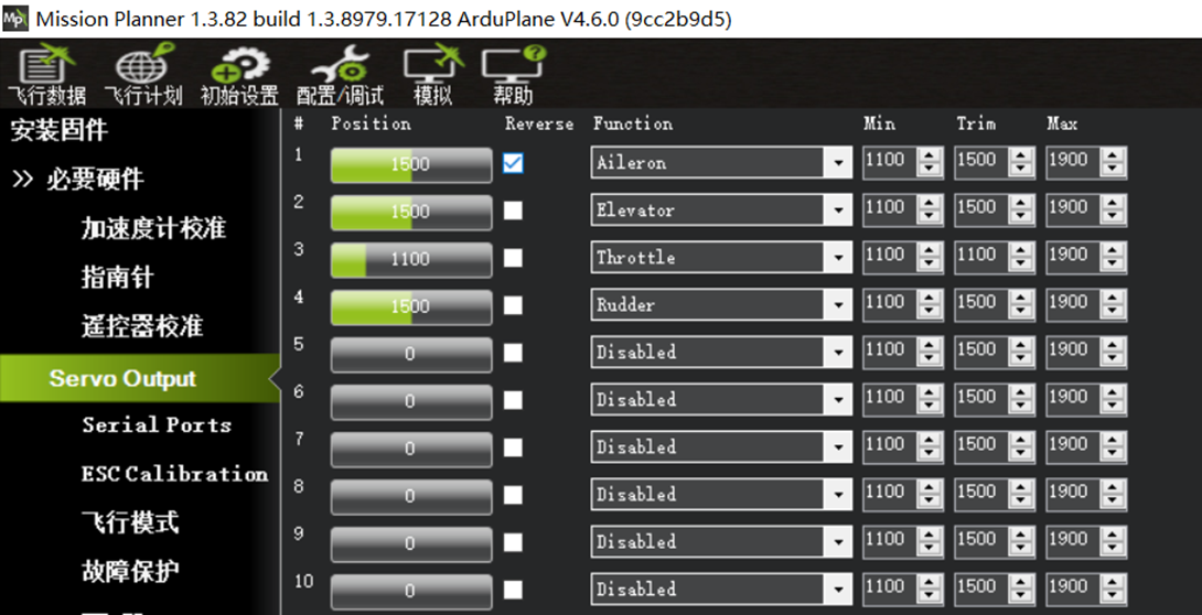 ArduPilot channel outputs operate in real time. During later control-surface correction checks, if the flight controller commands a channel in the wrong direction while correcting aircraft attitude, select Reverse for that channel to invert its output.
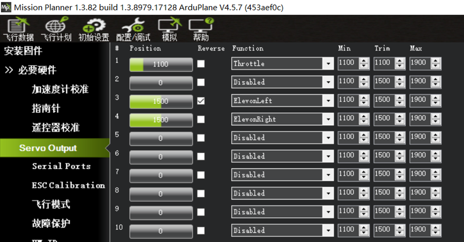 Example 1: For a single-motor pusher flying wing (such as ARWING or Freewing), if the left elevon servo is connected to S3, set #3 to ElevonLeft. If the servo moves in the wrong direction during setup, select Reverse for #3. If the ESC signal wire is connected to S1, set #1 to Throttle.
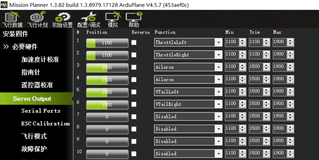 Example 2: A 3D-printed twin-motor V-tail aircraft using differential thrust.
Connect the two aileron servos to S3 and S4. Set both #3 and #4 to Aileron.
Connect the left-wing ESC signal to S1 and set #1 to ThrottleLeft. Connect the right-wing ESC signal to S2 and set #2 to ThroleLeft.
Connect the left V-tail servo to S5 and set #5 to VTailLeft. Connect the right V-tail servo to S6 and set #6 to VTatlRight.
Example 2: A 3D-printed twin-motor V-tail aircraft using differential thrust.
Connect the two aileron servos to S3 and S4. Set both #3 and #4 to Aileron.
Connect the left-wing ESC signal to S1 and set #1 to ThrottleLeft. Connect the right-wing ESC signal to S2 and set #2 to ThroleLeft.
Connect the left V-tail servo to S5 and set #5 to VTailLeft. Connect the right V-tail servo to S6 and set #6 to VTatlRight.
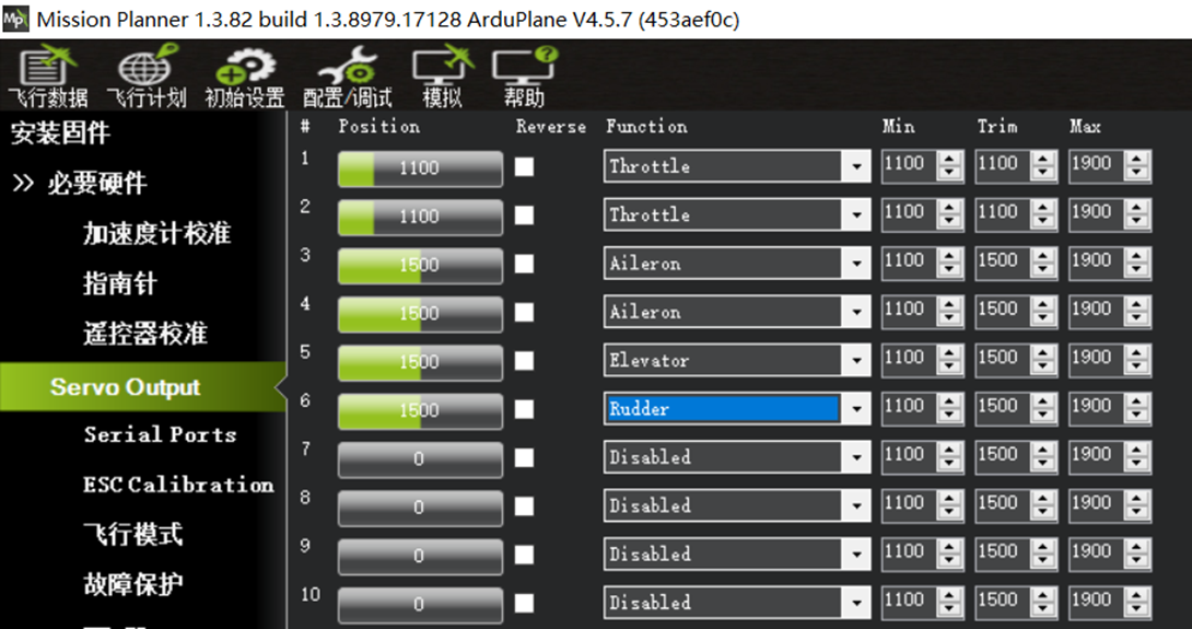
Example 3: A Great White Shark (Fatty) with a conventional wing and twin-motor power system, without differential thrust. Connect the two aileron servos to S3 and S4, and set both #3 and #4 to Aileron. Connect the two wing ESC signals to S1 and S2 in either order, and set both #1 and #2 to Throttle. Connect the horizontal-tail elevator servo to S5 and set #5 to Elevator. Connect the vertical-tail rudder servo to S6 and set #6 to Rudder.
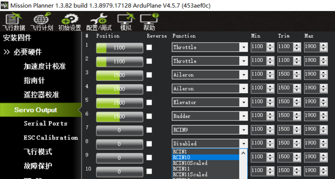 Example 4: To connect a servo gimbal to S8 for controlling the FPV camera viewing direction with radio transmitter channel 10 assigned to a custom knob, set #8 to RCIN10.
Section 5: Flight Controller Serial Port Assignments -- Serial Ports
Each serial-bus peripheral connected to the flight controller must be assigned to the appropriate interface. The default flight controller parameters are shown above. The first column, Port Name, identifies the corresponding serial port. For example, SERIAL PORT2 is serial port 2 (UART2). The Speed column specifies the baud rate for the interface.
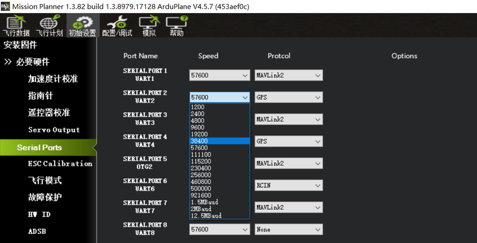
The Protcol column specifies the interface function. Set the appropriate Speed value and Protcol type for each serial peripheral.
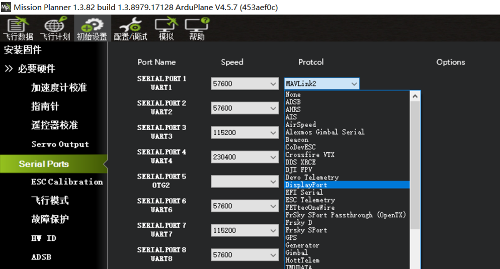
Receiver Configuration: For an SBUS receiver (for example, a WFLY WBUS, RadioLink-series, or Futaba-series receiver), connect a 2.54 mm 3-pin Dupont plug directly to RX6-4V5-GND on the flight controller. The SBUS interface corresponds to SERIAL PORT6 (UART6). With the default flight controller settings of 57600 and RCIN, the SBUS receiver signal is detected automatically.
An ELRS/CRSF receiver requires a 2.54 mm 4-pin Dupont connector.
Connect it to TX6-RX6-4V5-GND on the flight controller, which is the UART6 interface. Refer to page 10 of this guide for the wiring diagram.
Typical parameters for this type of receiver are 115200 and RCIN.
The flight controller firmware no longer supports PPM-signal or PWM-signal receivers.
GPS Module Configuration: A GPS requires a 2.54 mm 4-pin or 6-pin connector (6-pin when a compass is included). Connect it to SDA1-SCL1-TX2-RX2-4V5-GND on the flight controller, which is the UART2 interface. Refer to page 11 of this guide for the wiring diagram. Most GPS modules use 38400 and GPS. Some GPS modules support a Speed baud-rate value of 115200. A GPS without a compass uses only four wires: TX, RX, 5V, and GND.
Digital Video Air Unit Configuration:
A digital video air unit requires a 2.54 mm 4-pin connector connected to the flight controller TX1, RX2, 9V, and GND pins, corresponding to the UART1 interface. Refer to page 12 of this guide for the wiring diagram.
Typical digital video air-unit parameters are 115200 and DispiayPort.
This includes DJI air units compatible with DJI G2, G3, and N3 goggles; Caddx Avatar-series air units; and open-source OpenIPC HD video systems.
For older DJI air units and Vista used with DJI V1 or V2 goggles, set the Protcol value for UART1 to DJI FPV.
Onboard Bluetooth Telemetry-Link Module Configuration
The onboard Bluetooth telemetry-link module on the AET H743 Basic flight controller is connected directly to UART7.
Set this interface to 115200 and Mavlink2.
External Telemetry-Link Module Configuration
An external telemetry-link module should be connected to TX3 and RX3 on the flight controller, corresponding to the UART3 interface.
Typical telemetry-link parameters are 115200 and Mavlink2.
The following image shows the recommended settings for common peripheral interfaces.
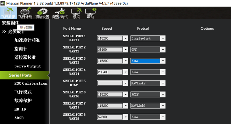 Connect the ELRS receiver to UART6.
Connect the digital HD video air unit to UART1.
Connect the GPS module to UART2.
Keep UART7 assigned to the flight controller’s onboard Bluetooth telemetry-link module.
After all serial peripherals are configured and wired correctly, the receiver and GPS module should be connected to the flight controller and configured. Use the following steps to verify that radio-control signals reach the flight controller through the receiver and that the GPS module is operating correctly.
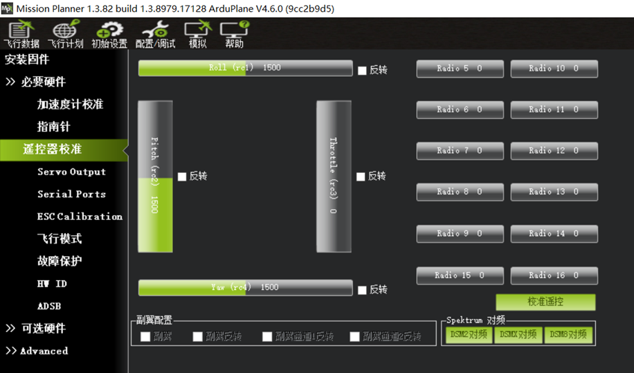
Section 6: Radio Transmitter Calibration If the radio transmitter is powered on and paired with the receiver, but the receiver-to-flight-controller wiring or serial-port configuration is incorrect, the Radio Calibration page will not show the Thrttle signal or channel values for channels 5~16, as shown below.
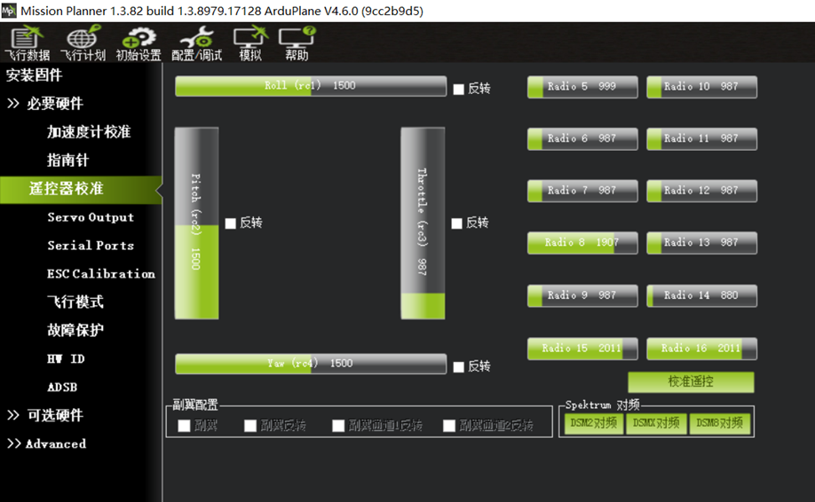
When the receiver is wired correctly and the corresponding serial port is configured correctly, green sliders are displayed for all channels.
Begin calibration of the radio transmitter sticks and other switch channels.
Click Calibrate Radio. A dialog displays “Ensure your transmitter is on and receiver is powered and connected. Ensure your motor does not have power/no props!!!” Confirm the direction of the radio transmitter throttle channel and ensure that the motor is unpowered and no propeller is installed. Click OK, as shown below.
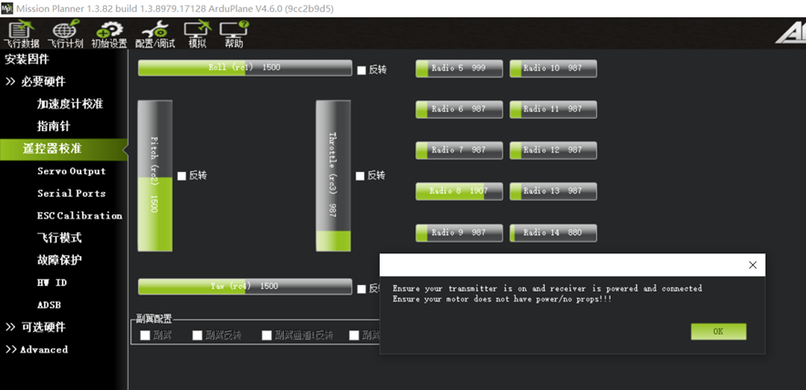
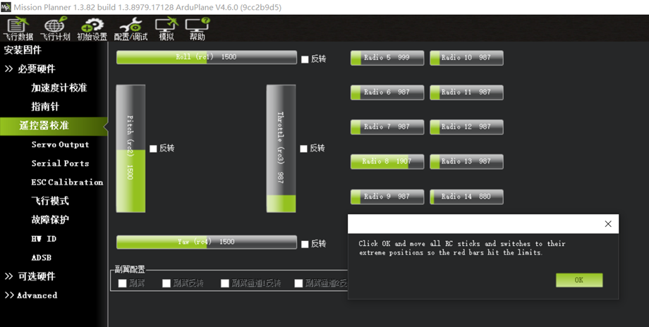
A dialog displays “Click OK and move all RC sticks and switches to their extreme positions so the red bars hit the limite”. After clicking OK, move every stick channel through its full range and move all switch channels, including the six-position switch, through all positions. Confirm that the red bars mark the maximum and minimum output values for each channel. Click OK, as shown below.
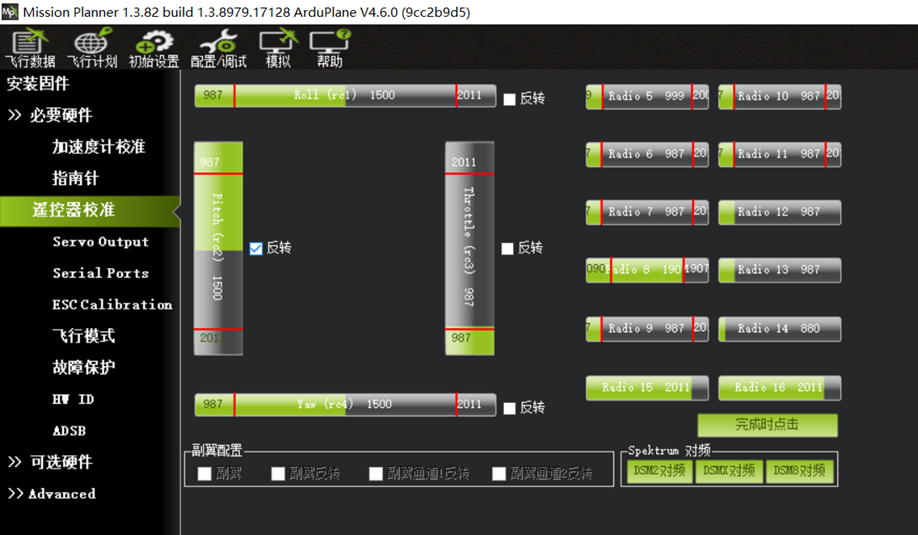
Move every stick through its full range and move all switch channels, including the six-position switch, through all positions. Confirm that red bars mark the maximum and minimum output values. Because of ArduPilot firmware behavior, selecting Reverse for Pitch rc2 is recommended. Click Click when Done, as shown below.
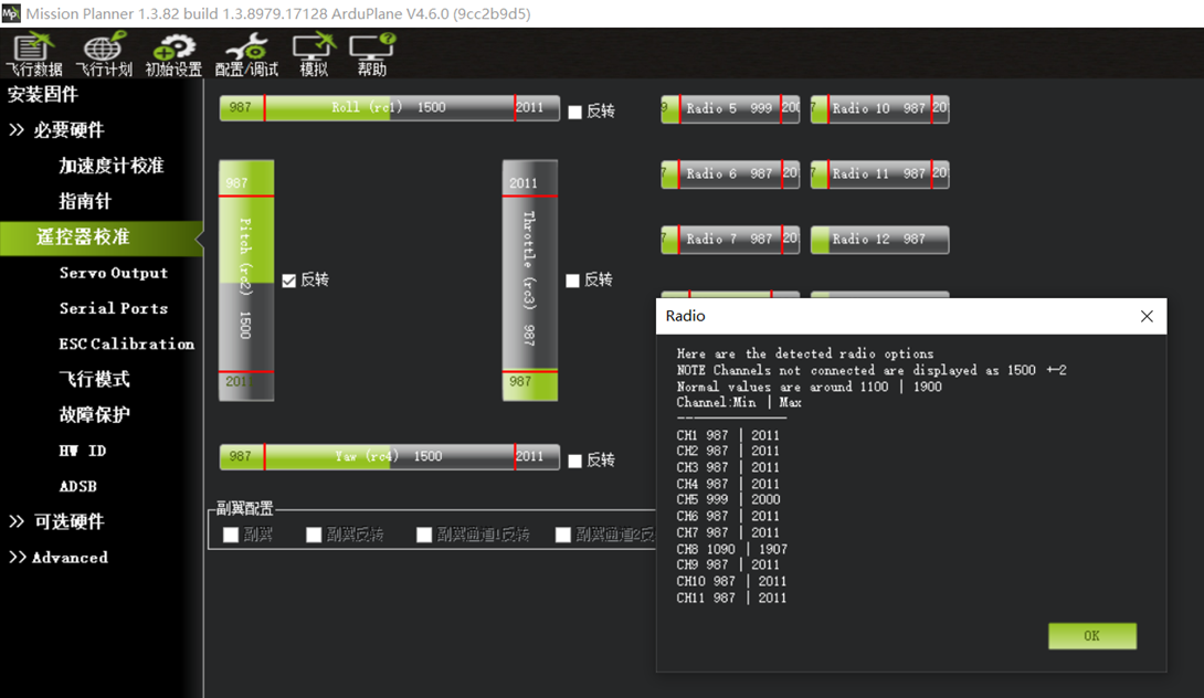
After clicking OK, a dialog displays the maximum and minimum input values for each channel. Click OK, as shown below.
Radio transmitter calibration is now complete.
Section 7: Verify the GPS Module Connection
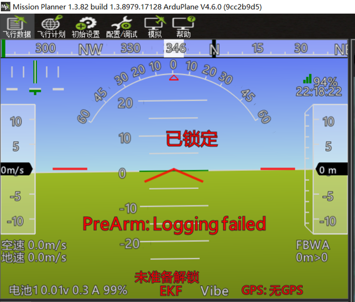
When the GPS is wired correctly, its serial port is configured correctly, and it is operating normally, check the lower-right corner of the attitude indicator on the ground-station home page.
The red message “GPS: No Fix” is displayed before a position fix is obtained. After satellite acquisition and positioning are completed outdoors, the white message GPS: 3D Fix is displayed.
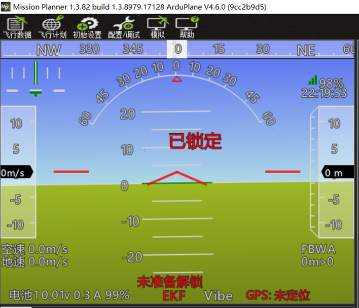 If the GPS wiring or serial-port configuration is incorrect, or if the GPS has a compatibility or hardware-quality issue, the flight controller cannot detect it correctly. The lower-right corner of the attitude indicator then displays the red message GPS: No GPS.
Section 8: Verify Flight Controller Orientation and Attitude Display
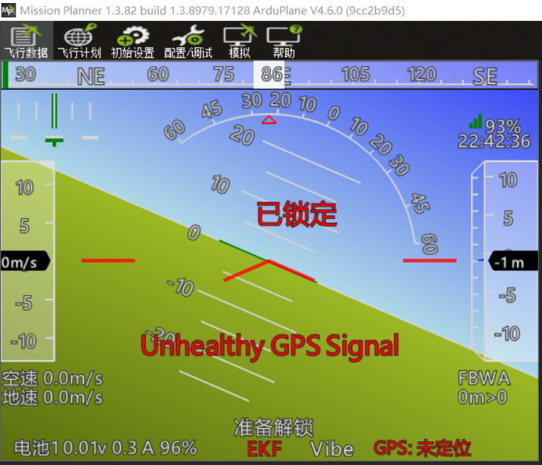
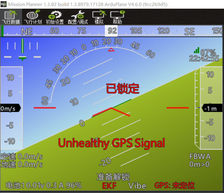
The attitude indicator in ArduPilot firmware represents the first-person view from the cockpit, not a third-person view of the aircraft.
The blue upper area represents the sky, the green lower area represents the ground, and the line between them is the horizon.
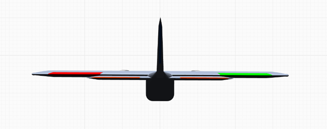
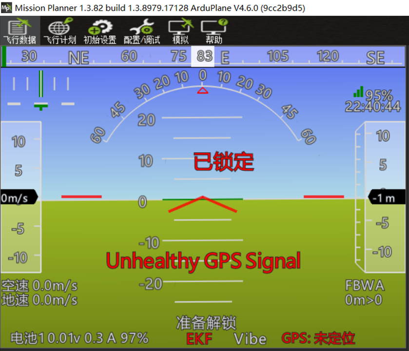 At this point, the aircraft or flight controller is level. The standard inspection viewpoint is from directly behind the aircraft, as shown below.
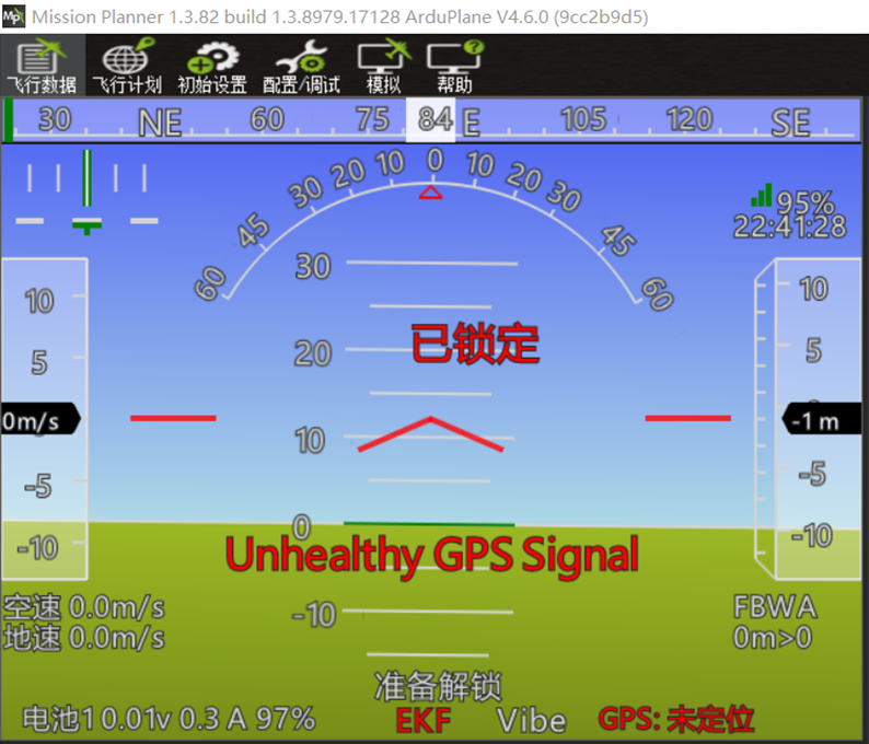
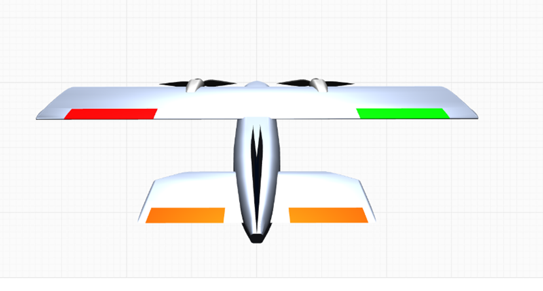
When the aircraft (or flight controller) pitches nose-up, the blue sky occupies more of the display and the green ground occupies less. The attitude indicator appears as follows:
The correct aircraft attitude is:
When the aircraft (or flight controller) pitches nose-down, the blue sky occupies less of the display and the green ground occupies more. The attitude indicator appears as follows:
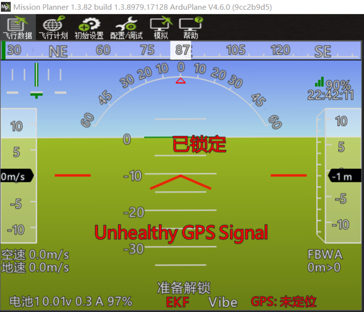
The correct aircraft attitude is:
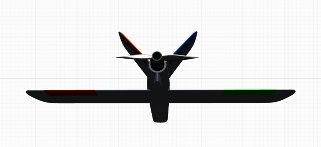
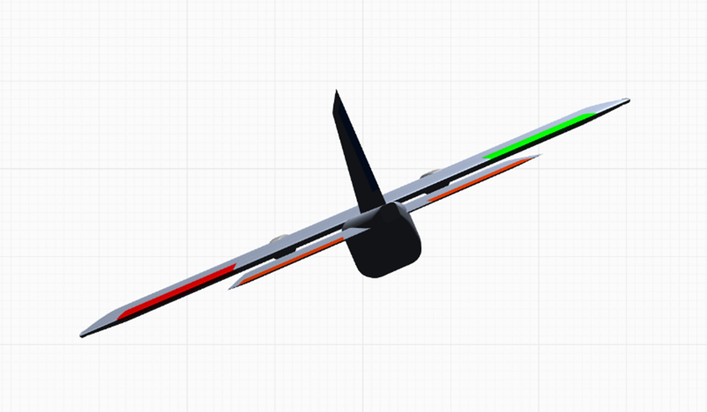
When the aircraft (or flight controller) rolls left, remember that the display represents the cockpit view. Visualize sitting in the cockpit while banking left and observe how the sky and horizon would move in the windshield. The correct attitude indicator is shown below:
 From a third-person viewpoint, the aircraft attitude should be:
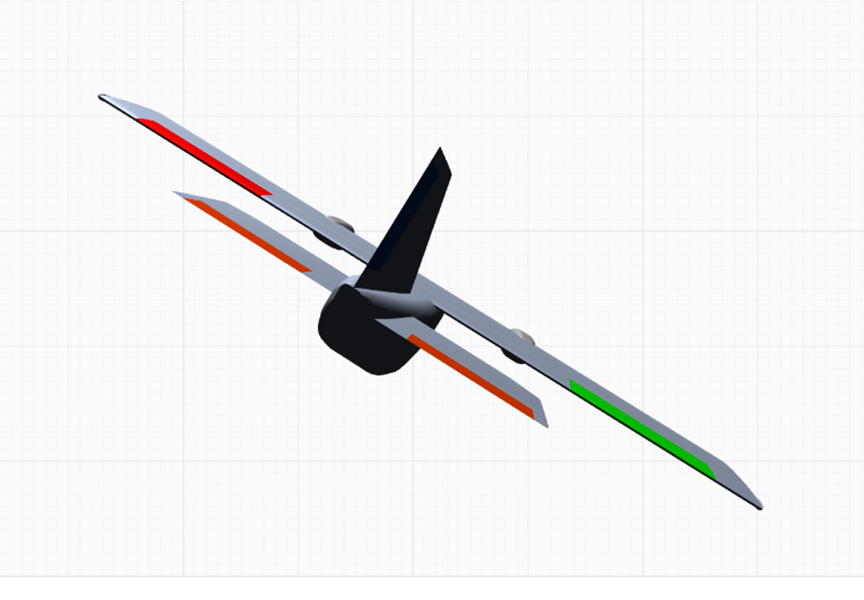
 When the aircraft (or flight controller) rolls right, remember that the display represents the cockpit view. Visualize sitting in the cockpit while banking right and observe how the sky and horizon would move in the windshield. The correct attitude indicator is shown below:
 From a third-person viewpoint, the aircraft attitude should be:
Section 9: Flight Mode Configuration ArduPilot uses one proportional channel to select six flight modes. The default mode-selection channel is radio transmitter channel 8. The image below shows the default value ranges for the mode-selection channel.
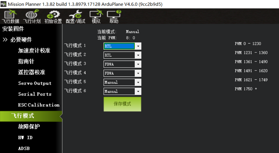
Use the drop-down arrow to the right of each flight-mode position to select the required flight mode.
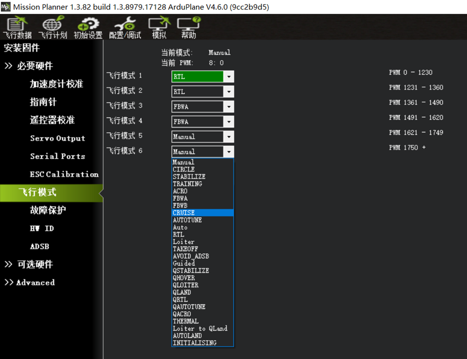 Characteristics of commonly used modes:
MANUAL: Manual mode with no flight-controller stabilization.
CIRCLE: Circle mode.
STABILIZE: Basic self-leveling mode. The flight controller returns the controls toward center and maintains level attitude, while the radio transmitter controls the aircraft attitude. Use this mode if FBWA response is too slow.
FBWA: Stabilized mode. The aircraft follows configured bank and pitch limits and maintains attitude effectively; altitude is controlled by throttle. Recommended for beginners.
FBWB: Stabilized altitude-hold mode. Adds effective altitude hold to FBWA behavior.
CRUISE: Cruise mode. Maintains altitude and heading; strongly recommended for long-range flight.
ACRO: Attitude-lock mode, similar to manual mode on an FPV racing drone. The commanded attitude is held when the sticks are released.
AUTOTUNE: Automatic configuration and tuning mode.
AUTO: Automatic waypoint mode.
LOITER: Loiter mode. The aircraft circles above the current position at the configured altitude and radius.
RTL: Return-to-launch mode. The aircraft returns in a straight line to the home position and circles above it at the configured altitude and radius.
TAKEOFF: Assisted hand-launch mode.
Based on broad user experience, the following flight-mode arrangement is recommended for fixed-wing aircraft.
Confirm that mode switching with the radio transmitter six-position switch operates correctly.
Recommended six-position switch assignments:
1. RTL return-to-launch mode.
2. FBWA stabilized mode.
3. CRUISE mode.
4. ACRO attitude-lock mode.
5. LOITER mode.
6. MANUAL mode.
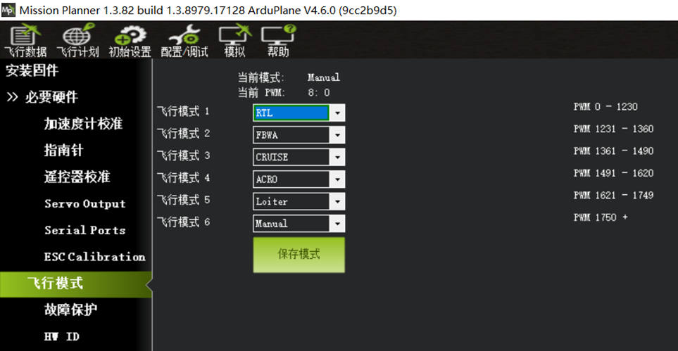 Some radio transmitters include a physical six-position switch, such as Jumper T16/T18 and Radiomaster TX16S. However, the output ranges of these switches do not align exactly with the six ArduPilot flight-mode ranges. Add a curve to the radio transmitter’s six-position proportional channel using the following values:
Six-Position Switch Curve Configuration
-100 -60 -20 20 60 100
-85 -45 -15 15 45 85
Some radio transmitters running the open-source EDGETX system provide six-position controls implemented as six independent buttons, including Radiomaster GX12 and BOXER, Jumper Tpro/T20S/T15, and Little Bee. Configure a mix for CH8 on the radio transmitter MIXER page. Refer to the operating video tutorial for the specific radio transmitter.
Some radio transmitters do not have a six-position switch, such as Frsky X9D, Jumper Tlite, Radiomaster TX12, and Zorro.
Use a three-position switch to select three commonly used flight modes, and use additional two-position or three-position switches to activate independent modes.
ArduPilot resolves flight-mode selection by applying the mode most recently activated.
Flight-Mode Switching with Independent Channel Switches
Example:
Use radio transmitter channel 8 (the flight controller default) with a three-position switch for mode selection. During configuration, assign the appropriate mode to each switch position.
Select FBWA stabilized mode, CRUISE altitude-and-heading mode, and LOTIER position-hold mode.
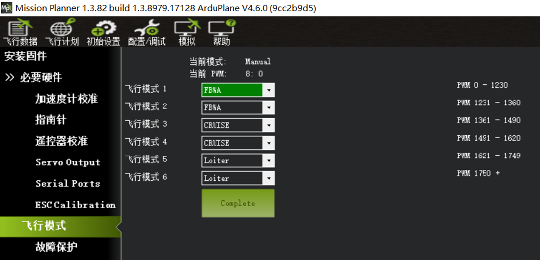
Use a two-position switch on radio transmitter channel 5 to activate TAKEOFF hand-launch mode.
Use a two-position switch on radio transmitter channel 6 to activate RTL return-to-launch mode.
For independent channel-switch flight-mode configuration, see page 66.
Section 10: Self-Stabilization Control-Surface Feedback Check and Radio Stick Control-Surface Check
This inspection can be performed only after the flight controller and servos are installed in the airframe and the control surfaces are mechanically connected to the servos.
Radio Transmitter Stick Mode
Left-Hand Throttle (Mode 2)
The left stick controls throttle vertically and rudder horizontally.
The right stick controls pitch/elevator vertically and roll/ailerons horizontally.
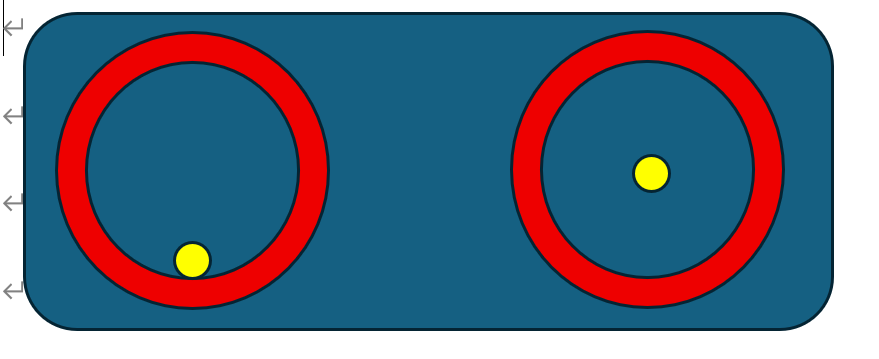
Right-Hand Throttle (Mode 1)
The left stick controls pitch/elevator vertically and rudder horizontally.
The right stick controls throttle vertically and roll/ailerons horizontally.
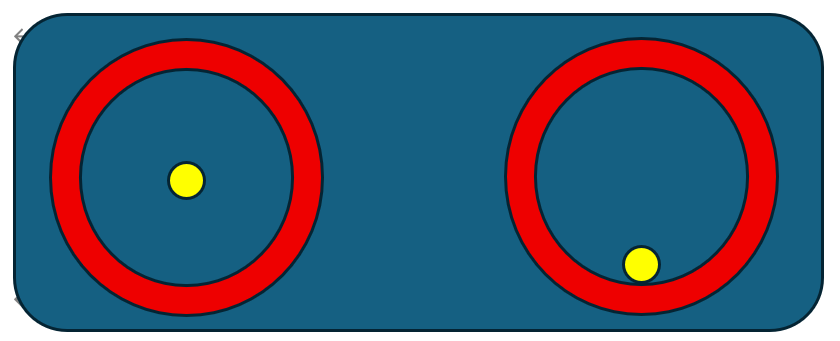
Self-Stabilization Control-Surface Correction Direction Check (Very Important)
Switch the flight controller to FBWA stabilized mode.
For Mode 2, set the left stick to minimum throttle with horizontal input centered, and center the right stick.
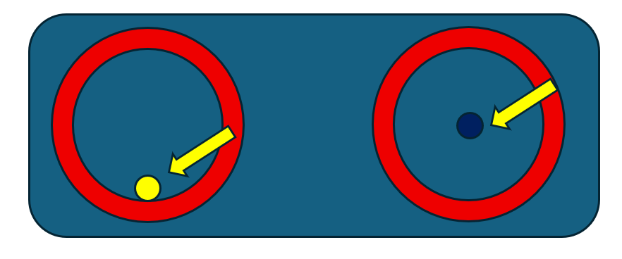
Lift the aircraft and move it as shown below. Verify that the control surfaces provide the following corrective feedback:
Conventional-layout aircraft, nose-up.
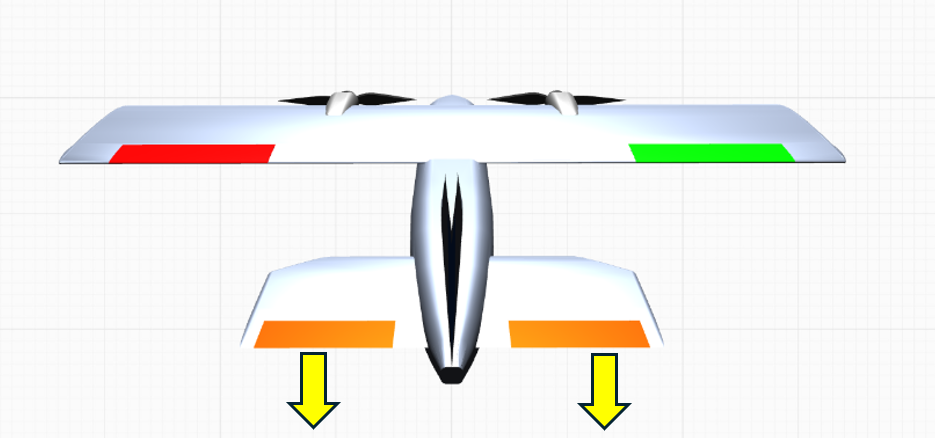
Flying-wing aircraft, nose-up.
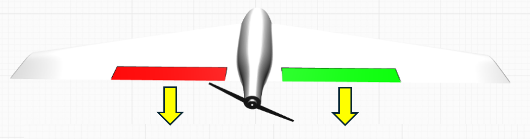
V-tail aircraft, nose-up.
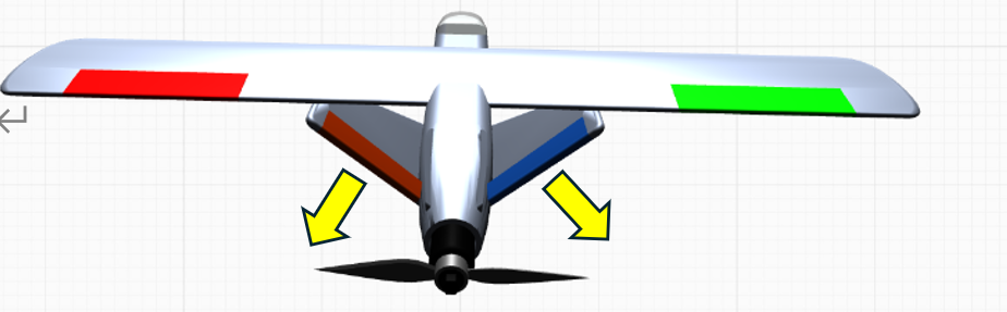
Conventional-layout aircraft, nose-down.
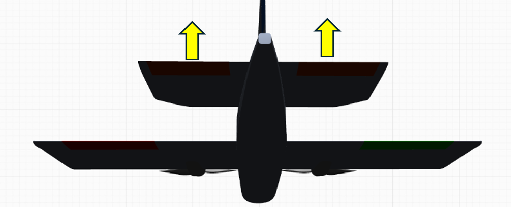
Flying-wing aircraft, nose-down.
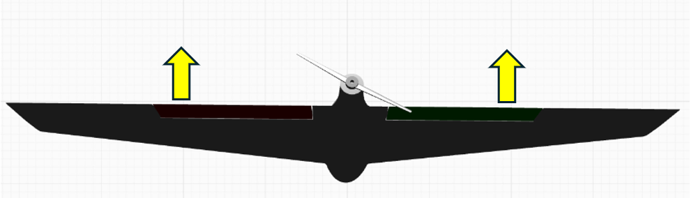
V-tail aircraft, nose-down.
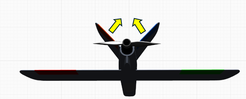
Conventional-layout aircraft, left roll.
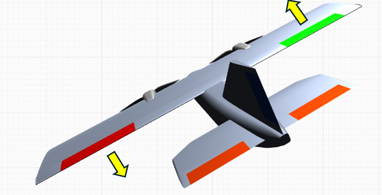
Flying-wing aircraft, left roll.
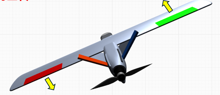
V-tail aircraft, left roll.
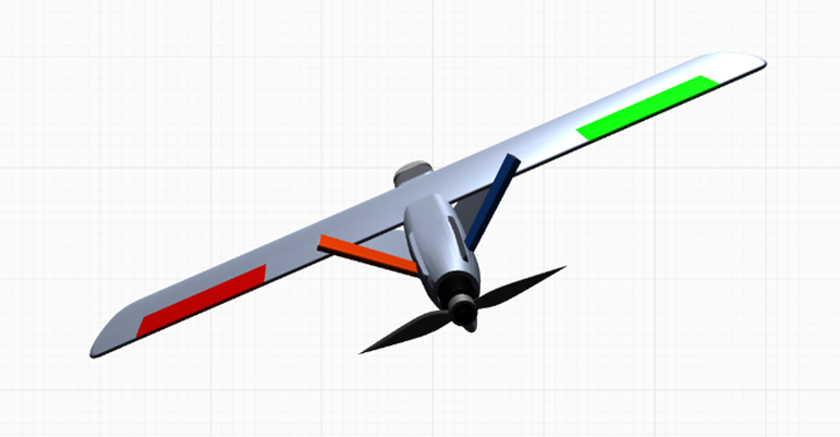
Conventional-layout aircraft, right roll.
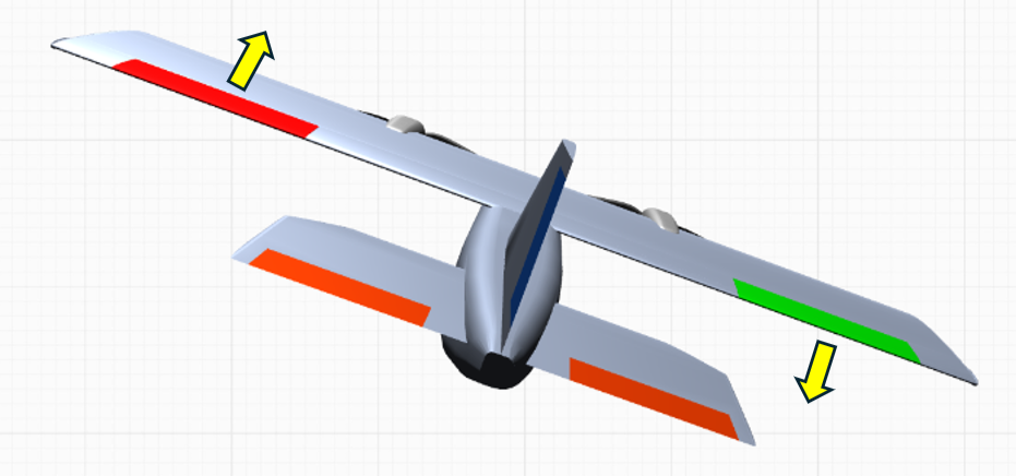
Flying-wing aircraft, right roll.
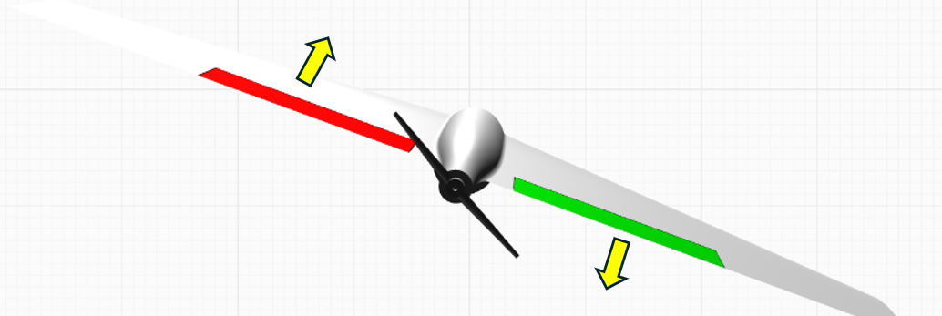
V-tail aircraft, right roll.
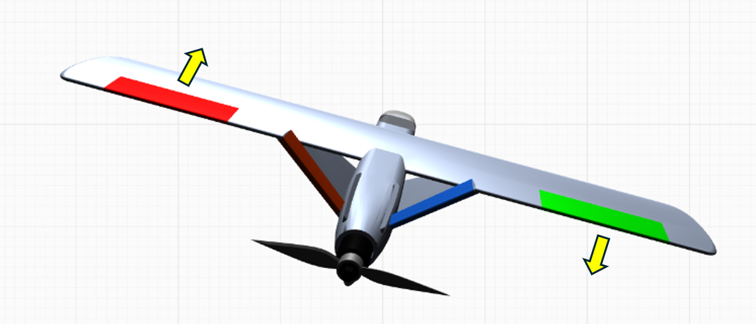
If any control-surface correction direction is incorrect, open the Servo Output page in the ground station and select Reverse for the corresponding channel. Repeat until all control-surface correction directions are correct.
For the radio stick control-surface check, switch the flight controller to MANUAL mode.
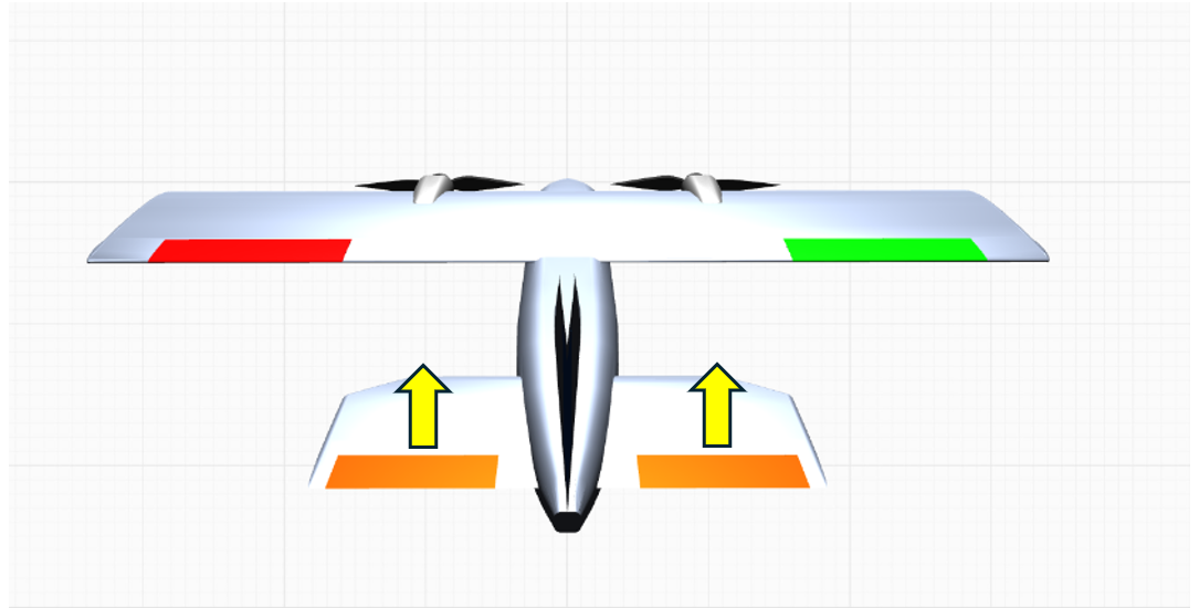
Move the right stick to its lowest position.
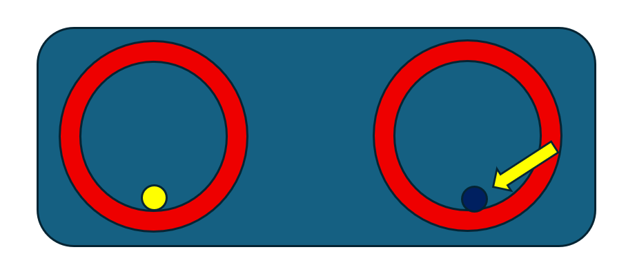
The aircraft control surfaces should respond as follows:
Conventional layout.
 Flying-wing layout.
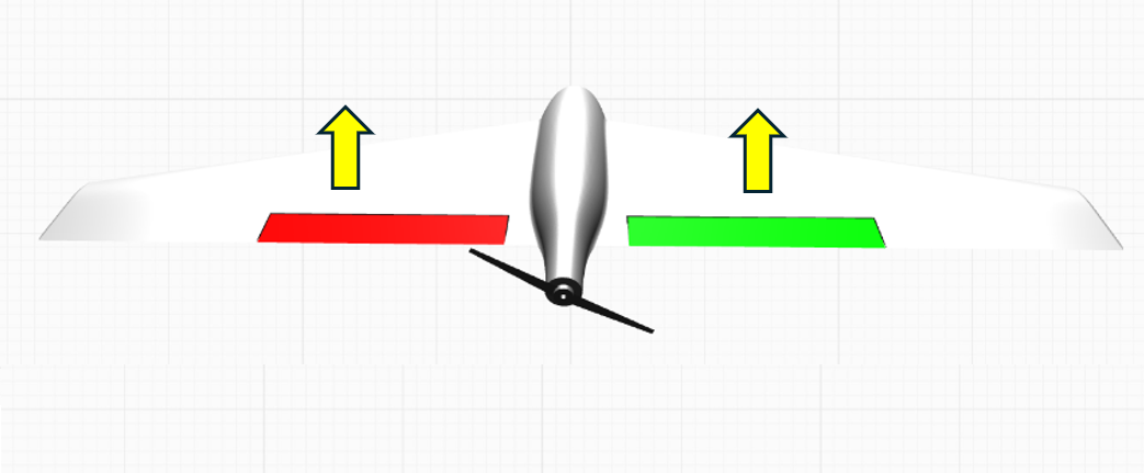 V-tail layout.
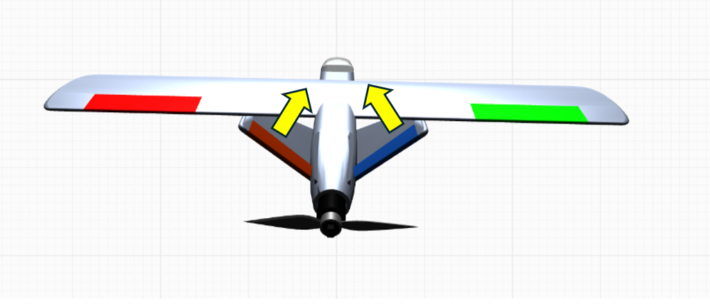
Move the right stick to its highest position.
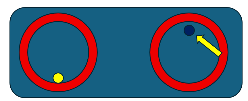
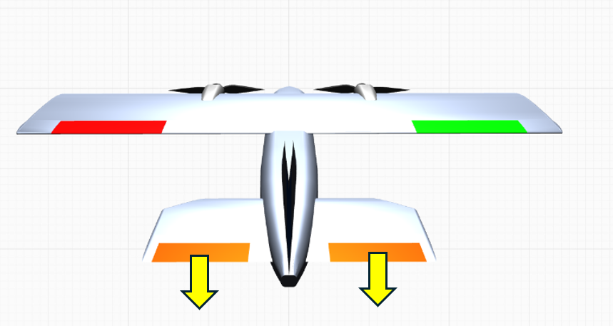
The aircraft control surfaces should respond as follows:
Conventional layout.
 Flying-wing layout.
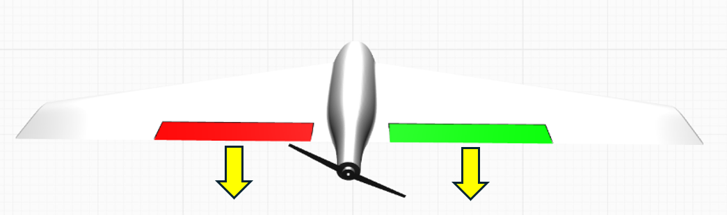 V-tail layout.
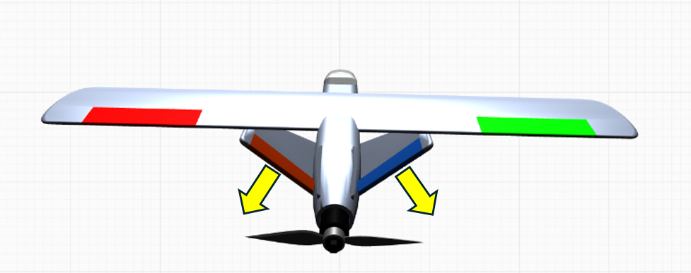
Move the right stick fully left.
The aircraft control surfaces should respond as follows:
Conventional layout.
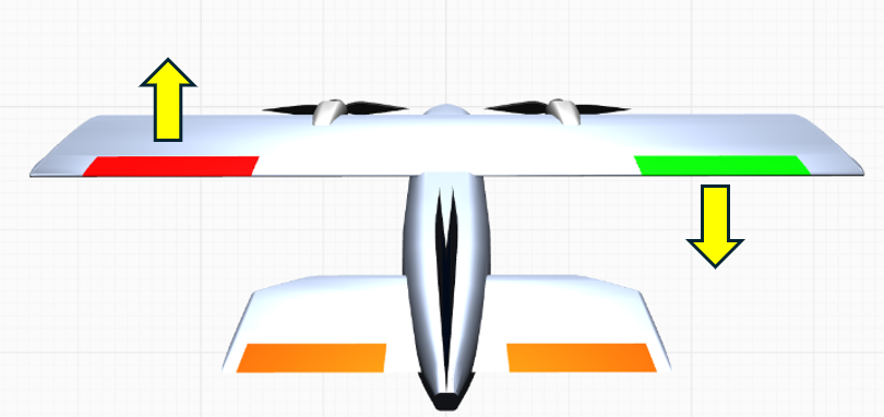 Flying-wing layout.
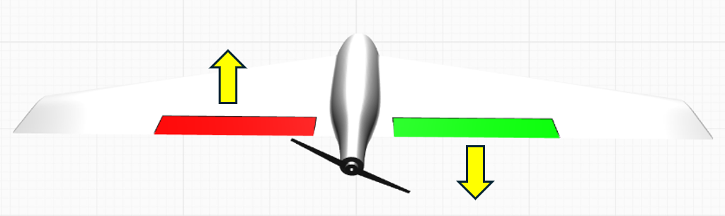 V-tail layout.
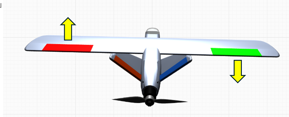
Move the right stick fully right.
The aircraft control surfaces should respond as follows:
Conventional layout.
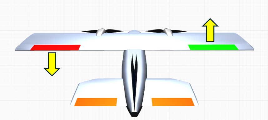 Flying-wing layout.
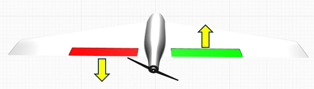 V-tail layout.
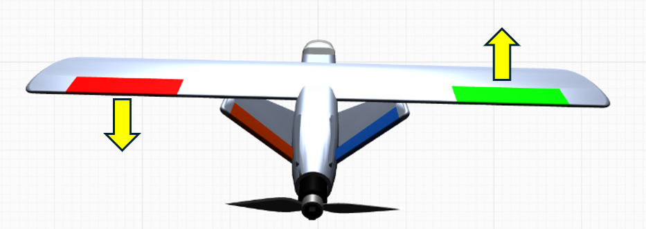 If control-surface response is reversed in MANUAL mode, open the Radio Calibration page, select the corresponding stick channel, and enable Reverse for that channel. See page 37.