Chapter 8: Full Parameter List Configuration
Most additional settings are configured individually in the "Full Parameter List", which is one of the defining features of ArduPilot firmware.
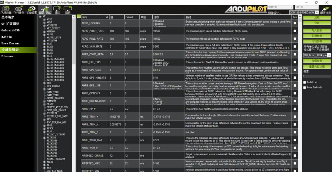
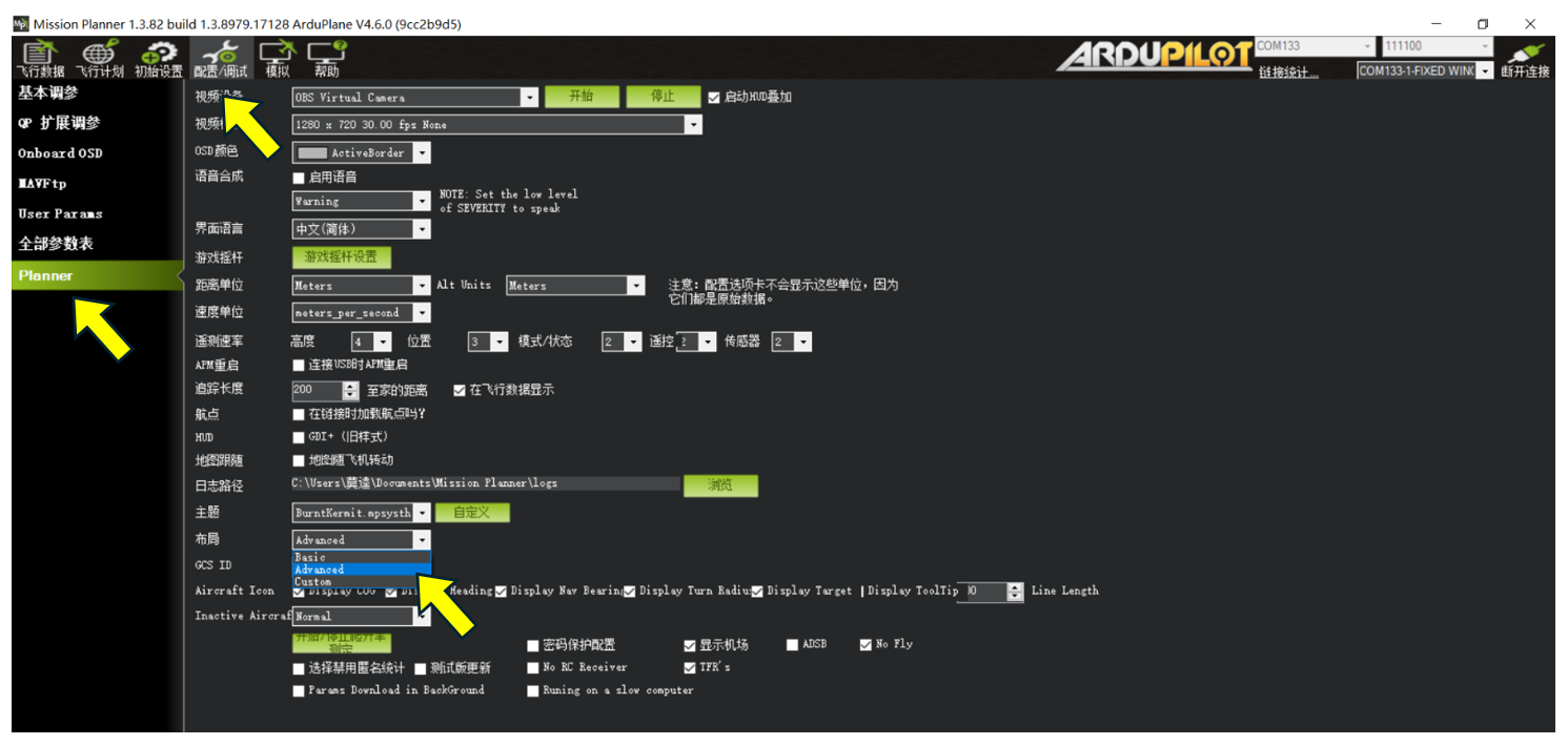
If "Full Parameter List" is not visible in Mission Planner, open the "Config/Tuning" page, select "Planner", set "Layout" to "Advanecd", and save. Close Mission Planner, reopen it, and reconnect the flight controller. The "Full Parameter List" page will then be available, as shown below.
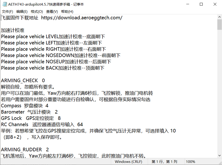
When using the Full Parameter List, keep the configuration notes TXT file open on the computer for reference.
Copy the required parameter name from the notes and paste it into the "Search" box on the right side of the Full Parameter List. The page refreshes to show the parameter current value, units, options, and English description. Modify the entry in the "Value" column, then click "Write Params" on the right. Some commands may display an additional dialog; close or dismiss it as appropriate. When the "Parameters successfully saved" dialog appears, click OK. The parameter value has now been updated.
Some parameter changes require a flight controller restart before they take effect.
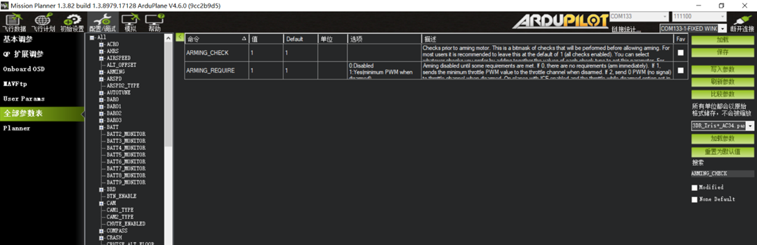
Section 1: Arming Checks with ARMING_CHECK and Disarming with ARMING_RUDDER
ArduPilot applies strict arming requirements. With default settings, dozens of checks must pass before the flight controller can arm. (Search for ARMING.)
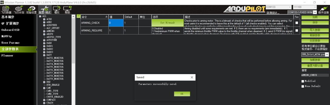
ARMING_CHECK 0 (Critical: Use only for ground testing. Never disable all arming checks for actual flight, as this can result in loss of the aircraft.)
This disables all arming checks. In modes without automatic throttle control, such as FBWA and Manual, hold throttle at minimum and full right Yaw for 6 seconds to arm the flight controller. The motor will then respond to throttle. Modes with automatic throttle control, including RTL, CRUISE, and Loiter, cannot be armed using this stick command.
To retain checks for selected critical functions, enable the required options according to the aircraft configuration.
Compass module: 4
Barometer module: 2
GPS Lock: 8
RC Channels input: 64
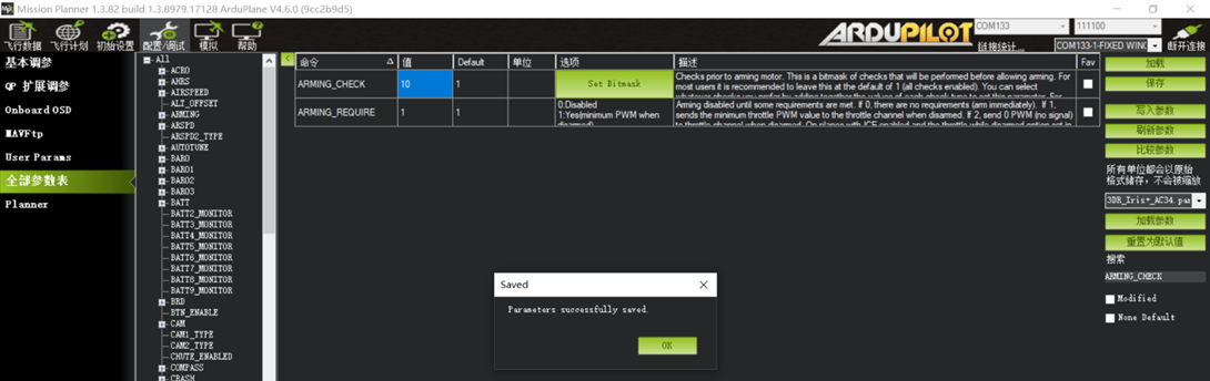
Example: To require both a valid GPS lock and a healthy barometer before arming, enter 10 (8 + 2), then write and save the parameter.
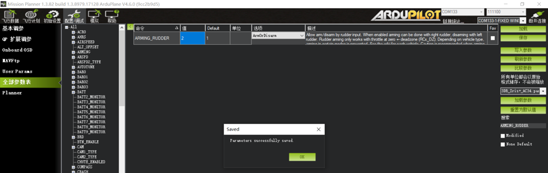
Set ARMING_RUDDER to 2. After landing, hold full left Yaw for 6 seconds to disarm the flight controller. The motor will no longer respond to throttle.
Section 2: Video Link OSD Parameters
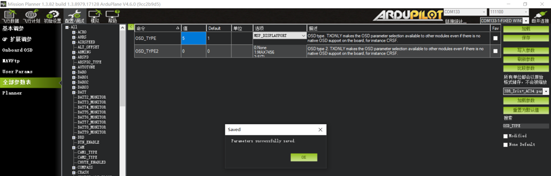
OSD_TYPE
This parameter selects the OSD display mode used by the video link.
For a standard analog 5.8G video link, keep the default value of 1.
For digital video links using MSP_Displayport, including air units compatible with DJI G2/G3/N3 goggles, Walksnail Avatar air units, and open-source OpenIPC digital HD air units, set this parameter to 5.
For older DJI HD Goggles V1/V2 with Vista or the original dual-antenna air unit, set this parameter to 3.
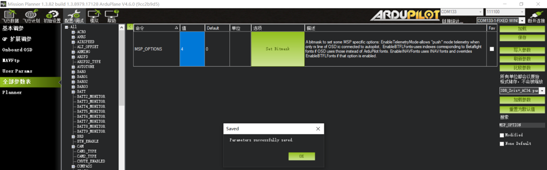
MSP_OPTIONS 4 This parameter must be configured for air units compatible with DJI G2/G3/N3 goggles.
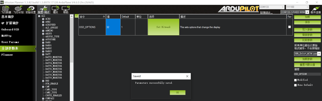
OSD_OPTION 32
This parameter must be configured for air units compatible with DJI G2/G3/N3 goggles.。
For an open-source OpenIPC digital air unit, set this parameter to 42.
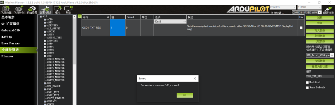
OSD1_TXT_RES 1
This parameter adjusts the OSD resolution and layout. It is recommended for all HD video links.
Section 3: Changing the Default Six-Position Mode Channel with FLTMODE_CH
The firmware uses channel 8 as the flight-mode channel by default. Configure radio channel 8 as a six-position switch for mode selection. With an ELRS receiver, use ELRS 3.X or later in 100Hz Full or 333Hz Full mode. FLTMODE_CH can remain at the default value of 8.
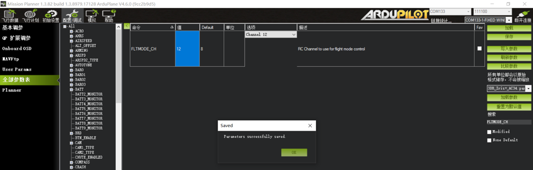
To use another channel for the six-position mode switch, set FLTMODE_CH to that channel number. For example, set FLTMODE_CH 12 and configure radio channel 12 as the six-position mode switch.
Section 4: Changing Maximum Attitude Angles in FBWA Mode
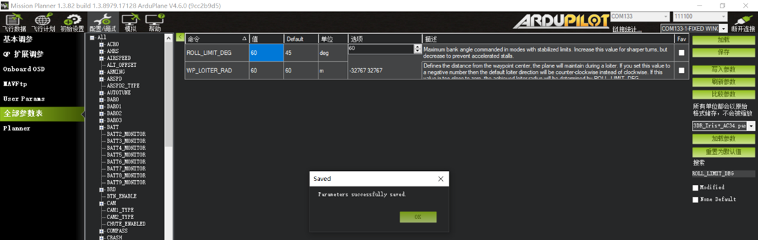
ROLL_LIMIT_DEG 60 Maximum roll angle in FBWA mode. Default: 45.
A value of 60 is recommended to reduce the turning radius during FBWA roll maneuvers.
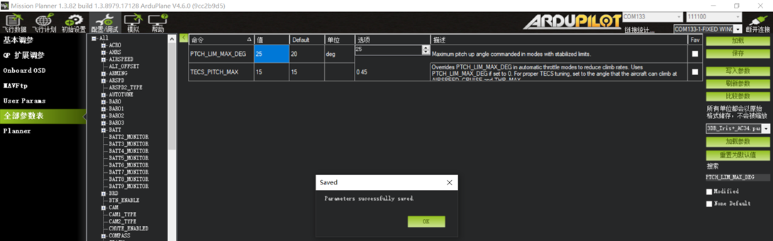
PTCH_LIM_MAX_DEG 35 Maximum pitch angle in FBWA mode.
Default: 20. A value of 35 is recommended to allow a steeper climb angle and increase climb rate in FBWA mode.
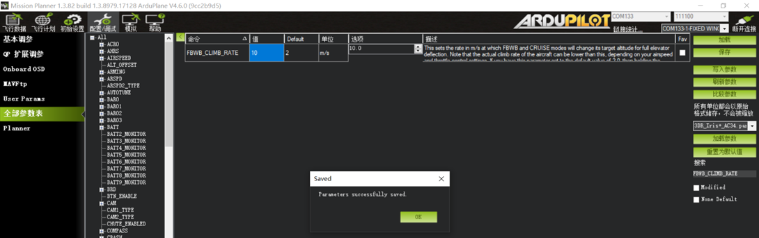
FBWB_CLIMB_RATE 4 110m/s. CRUISE altitude-and-heading mode is commonly used for long-range flight. The default permitted climb rate is only 2M/s. Adjust this parameter according to the aircraft power system. In CRUISE mode, a pitch-up command from the radio transmitter makes the aircraft climb at the configured rate. A value of 510m/s is recommended.
Section 5: Adjusting Control-Surface Travel for Mixed-Control Airframes with MIXING
This applies to flying-wing airframes using elevon mixing and V-tail airframes using elevator-rudder mixing.
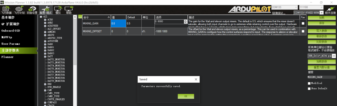
The default flight controller settings provide limited control-surface travel. Increase MIXING_GAIN to increase travel. The default is 0.5; values of 0.8 or 1 may be used as appropriate.
Section 6: Selecting Modes with Independent Channel Switches (see page 49)
An independent radio channel switch can be assigned to activate a specific mode. Common option values are listed below:
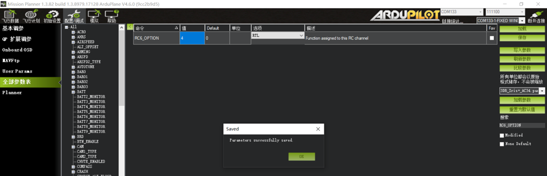
4 : ModeRTL return-to-launch mode
16 : ModeAuto waypoint mission mode
51 : ModeManual manual mode
56 : ModeLoiter position loiter mode
58 : Clear Waypoints
72 : ModeCircle circling mode
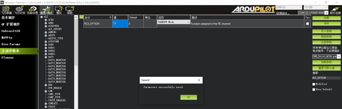
77 : ModeTakeoff hand-launch mode
92 : FBWA stabilized mode
150 : CRUISE altitude-and-heading mode
153 : ArmDisarm switch for one-action arming/disarming
Examples:
To use a two-position switch on radio channel 5 for TAKEOFF hand-launch mode, find RC5_OPTION in the Full Parameter List and select 77.
To use a two-position switch on radio channel 6 for RTL mode, find RC6_OPTION in the Full Parameter List and select 4.
Section 7: TAKEOFF Hand-Launch Mode Parameters (TK)
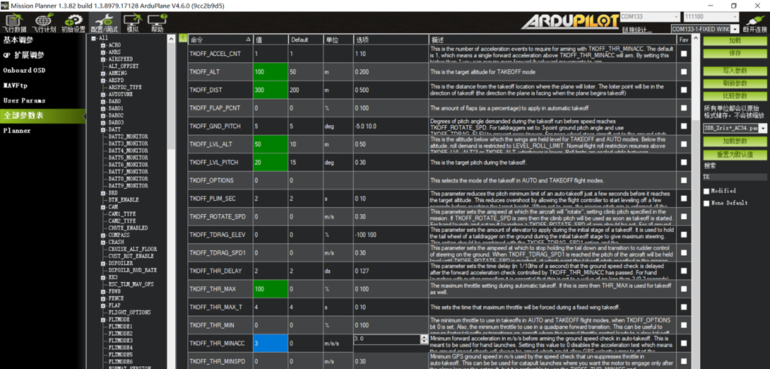
TAKEOFF hand-launch mode is useful for hand-launched FPV aircraft. After assigning a switch to this mode, configure the relevant launch parameters as needed.
Recommended parameters:
TKOFF_ALT 100 (Set the TAKEOFF target altitude to 100 m.)
TKOFF_DIST 300 (Set the maximum TAKEOFF distance to 300 m.)
TKOFF_LVL_ALT 50 (After launch, keep the wings level when the first-stage altitude is reached. Default: 20.)
TKOFF_LVL_PITCH 20 (Set the maximum TAKEOFF climb angle to 20°.)
TKOFF_THR_MAX 100 (Set the maximum TAKEOFF throttle to 100%.)
TKOFF_THR_MINACC 3 (The flight controller enables throttle output when it detects an instantaneous launch speed of 3 m/s.)
TAKEOFF mode can be activated only after a valid GPS position is obtained and the flight controller is armed successfully.
Section 8: Failsafe Parameters (FS) - Critical
ArduPilot triggers the failsafe when the receiver throttle output detected by the flight controller falls below 1000. Users familiar with INAV or Betaflight will recognize that when the radio transmitter is not linked to the receiver, or the flight controller does not detect the receiver, throttle is typically fixed at 885. The default firmware uses conservative failsafe settings, so perform a failsafe check as shown below. (Search for FS.)
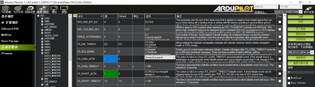
FS_SHORT_TIMEOUT 1.5 (After receiver throttle output is lost for 1.5 seconds, the flight controller executes the first-stage failsafe action.)
FS_SHORT_ACTN 1 (First-stage failsafe action: enter CIRCLE mode and wait. Default: 0, "No action".)
FS_LONG_TIMEOUT 5 (If throttle output is not restored within 5 seconds after the first-stage failsafe begins, execute the second-stage failsafe action.)
FS_LONG_ACTH 1 (Second-stage failsafe action: execute RTH. Default: 0, "Continue current action".)
Section 9: Return and Loiter Parameters
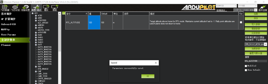
ArduPilot uses a default loiter altitude of 100 m at the return point. Adjust this value for local terrain and operating conditions. During RTL, the aircraft flies a straight path toward the launch point while descending.
If the current altitude is below the configured RTL altitude, the aircraft climbs rapidly to that altitude before returning.
Configure the return altitude as follows:
RTL_ALTITUDE 120 m Default: 100 m. This is the loiter altitude after RTL reaches the launch point. Set this parameter to -1 to return at the aircraft current altitude and loiter above the launch point.
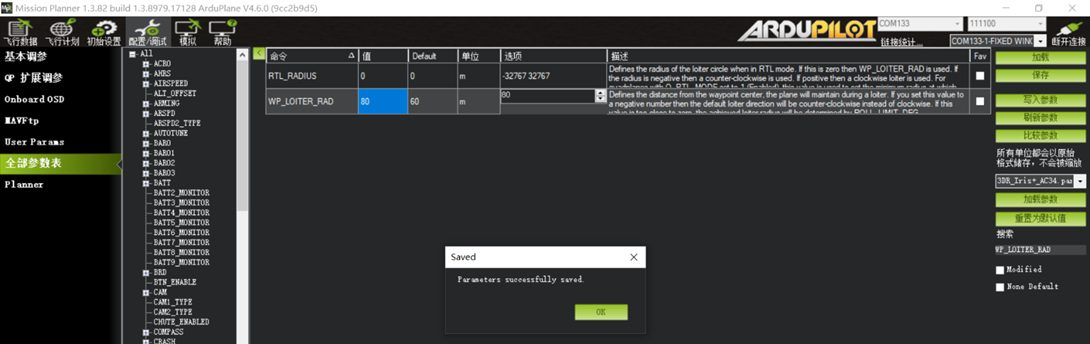
After returning above the launch point, the aircraft enters a loiter circle. The circle parameters can also be adjusted. WP_LOITER_RAD 80 Loiter radius. Default: 60 m.
A positive value produces clockwise loiter; a negative value produces counterclockwise loiter. This radius applies to both RTL and Loiter modes.
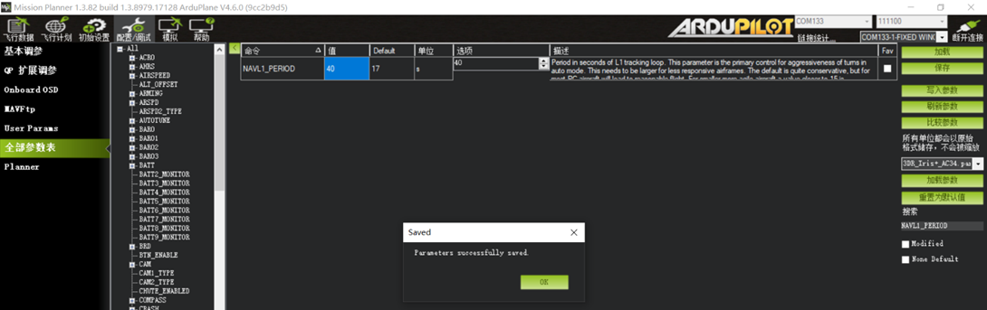
For example, with an 80 m radius and a 40-second orbit, throttle and airspeed during loiter are relatively efficient.
Section 10: Flight Controller Mounting Orientation with AHRS_ORIENTATION
Some airframes cannot accommodate the default horizontal flight controller orientation. This is common when converting scale aircraft to FPV and no mounting location was designed for a flight controller. The unit may need to be mounted on the side of the fuselage or inverted on the bottom. Set AHRS_ORIENTATION to match the actual mounting orientation.
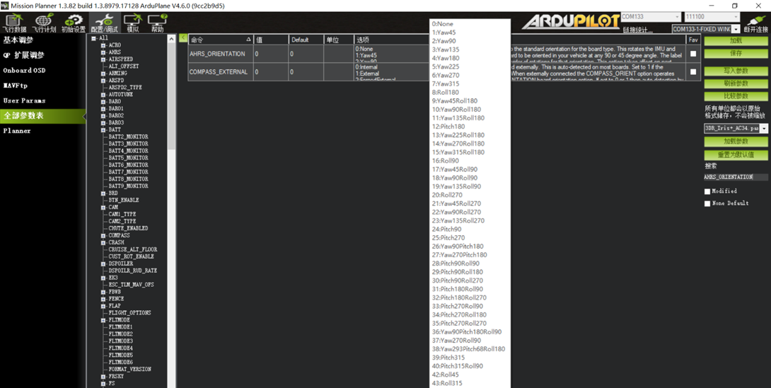
Example 1: If the main power cable direction, which normally points toward the nose, points aft because the flight controller is installed backward, set the parameter to 4 (YAW 180).
Example 2: If the bottom of the flight controller is attached to the fuselage side, equivalent to a 90-degree or 270-degree rotation around the ROLL axis, set the parameter to 16 or 20.
Example 3: On the Swordfish airframe, the flight controller must be inverted with its default nose direction pointing aft. This corresponds to ROLL 180 plus YAW 180. Because no exact option is provided, PITCH 180 produces the required orientation in practice. Set the parameter to 12.