Chapter 3: Basic Configuration and Tuning - Six-Position Calibration, Compass, Servo, and Motor Setup
Section 1: Connect the Ground Station and Reset Default Parameters. Open the MissionPlanner configuration and tuning software.
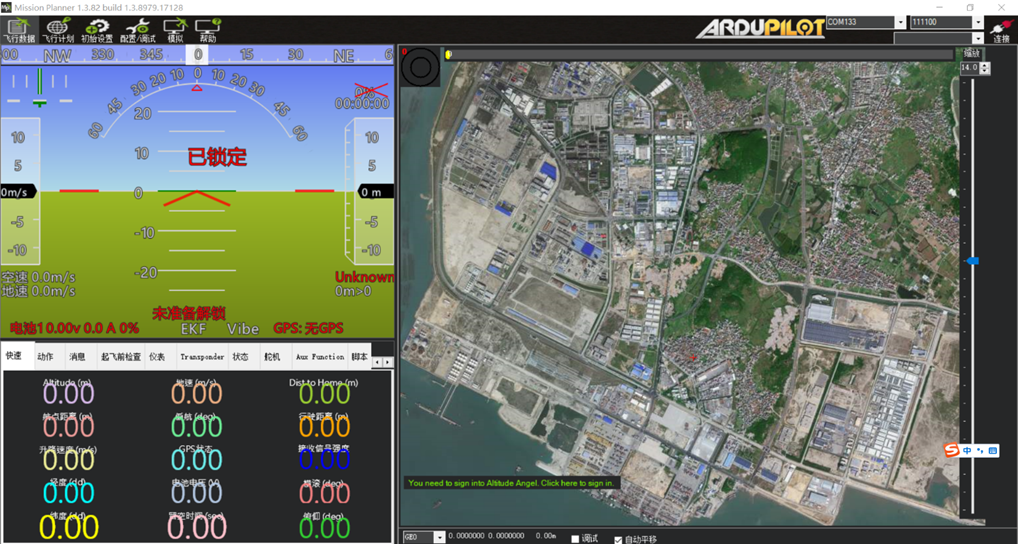 If the live satellite map does not load, open the ground station “Flight Plan” page and select the map source on the right. “Amap Satellite Map” is generally recommended. After selecting it, close the ground station and restart MissionPlanner. The ground station will then load “Amap Satellite Map” online.
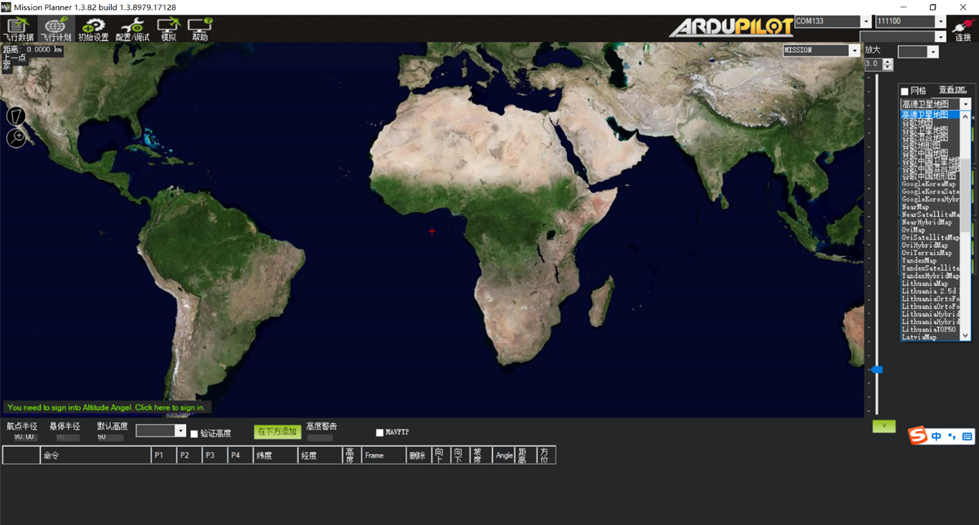
Connect the flight controller to the computer with a Type-C data cable. In the upper-right corner of MP, select the port assigned to the flight controller, as shown below:
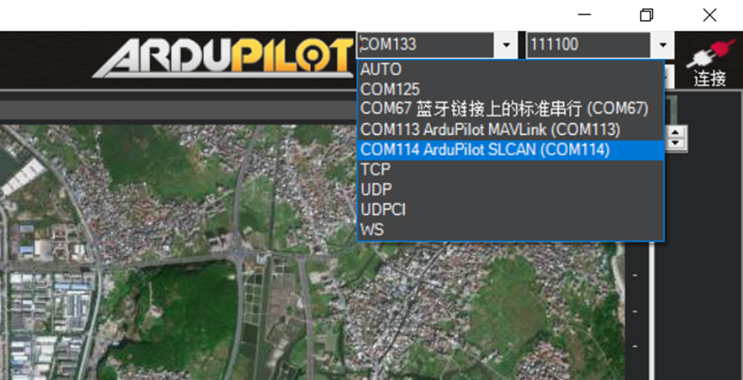 Click Connect and wait several seconds while the software reads data from the flight controller.
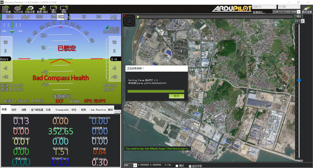 Connection successful.
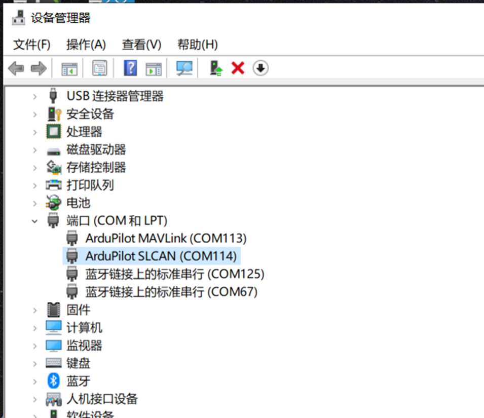
If the flight controller does not appear in the port drop-down menu after USB is connected, verify that the computer has recognized the flight controller driver and assigned a port. Check the Ports section in Windows Device Manager. If no port number is assigned, install the appropriate driver.
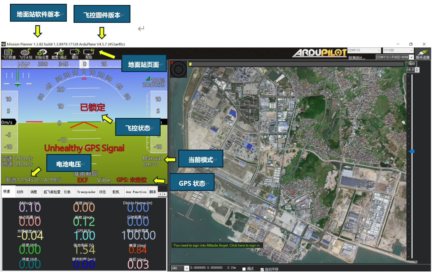
The image below provides an overview of the first configuration and tuning page.
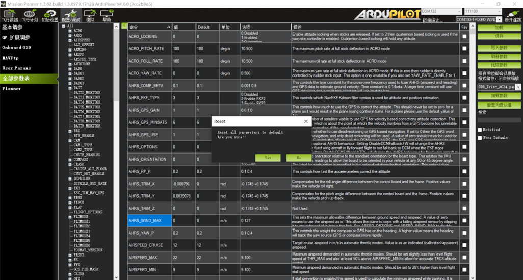
After flashing new firmware, we strongly recommend performing “Reset to Default Parameters” once before configuration.
Navigate to “CONFIG/TUNING” → “Full Parameter List” → “Reset to Default Parameters.”
Click the option once. When the ground station requests confirmation, click Yes.
Section 2: Accelerometer and Level Calibration
Click Initial Setup, then Accelerometer Calibration.
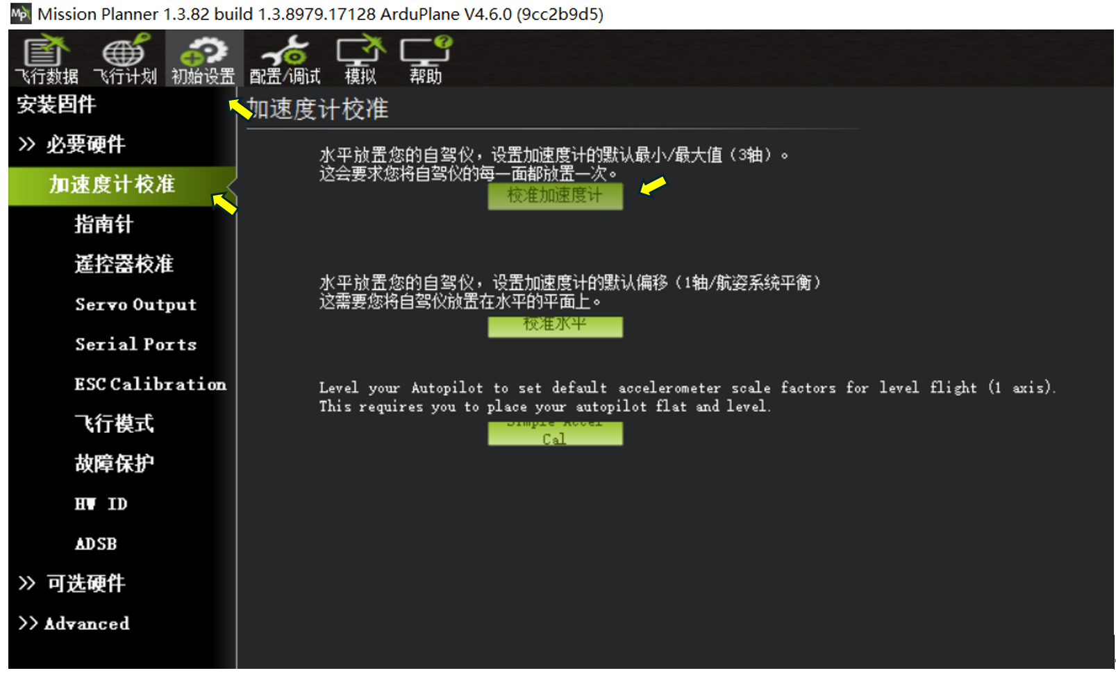
Click Calibrate Accelerometer. Follow the software prompts and place the flight controller on each of its six sides to complete six-position calibration, as shown below.
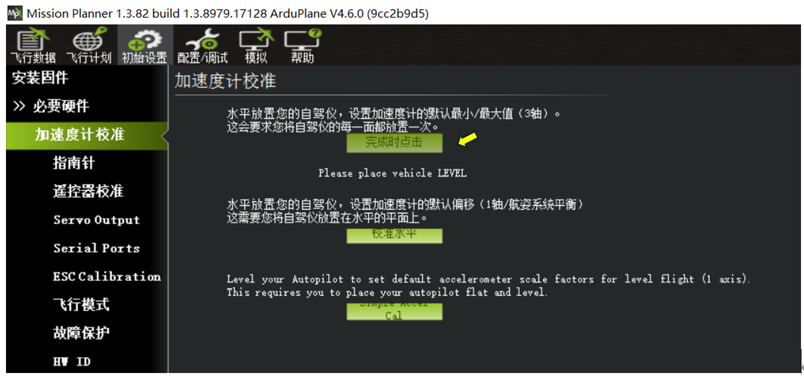
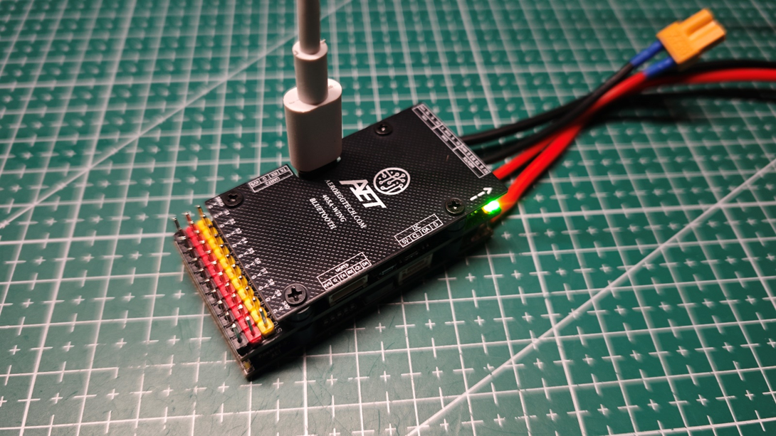
Please place vehicle LEVEL - accelerometer calibration with the bottom side facing down, as shown below.
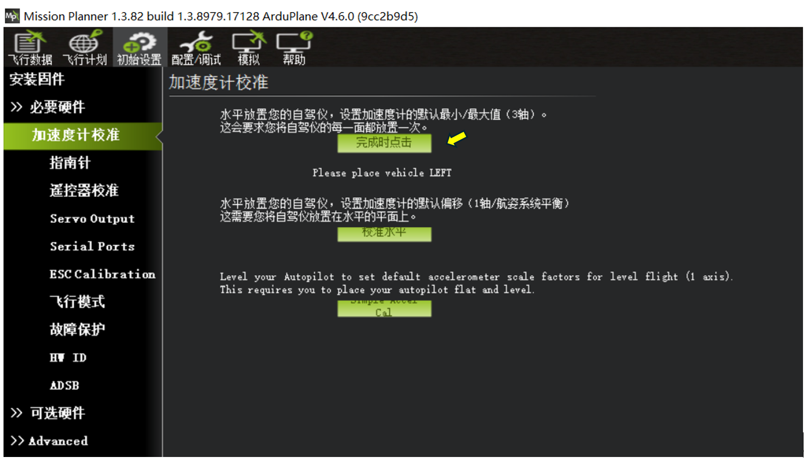
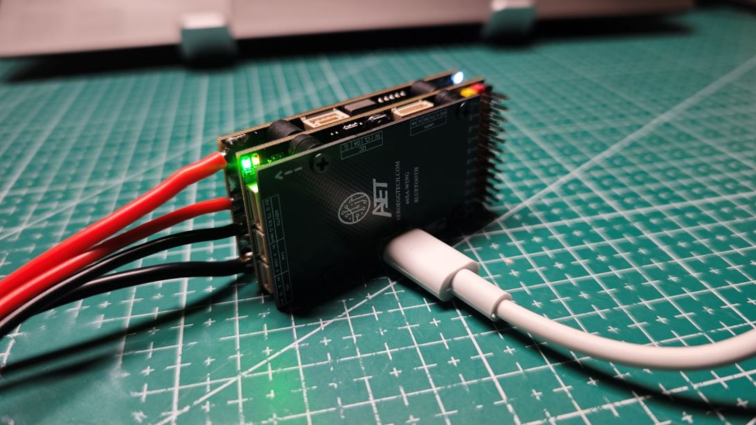
Please place vehicle LEFT - accelerometer calibration with the left side facing down, as shown below.
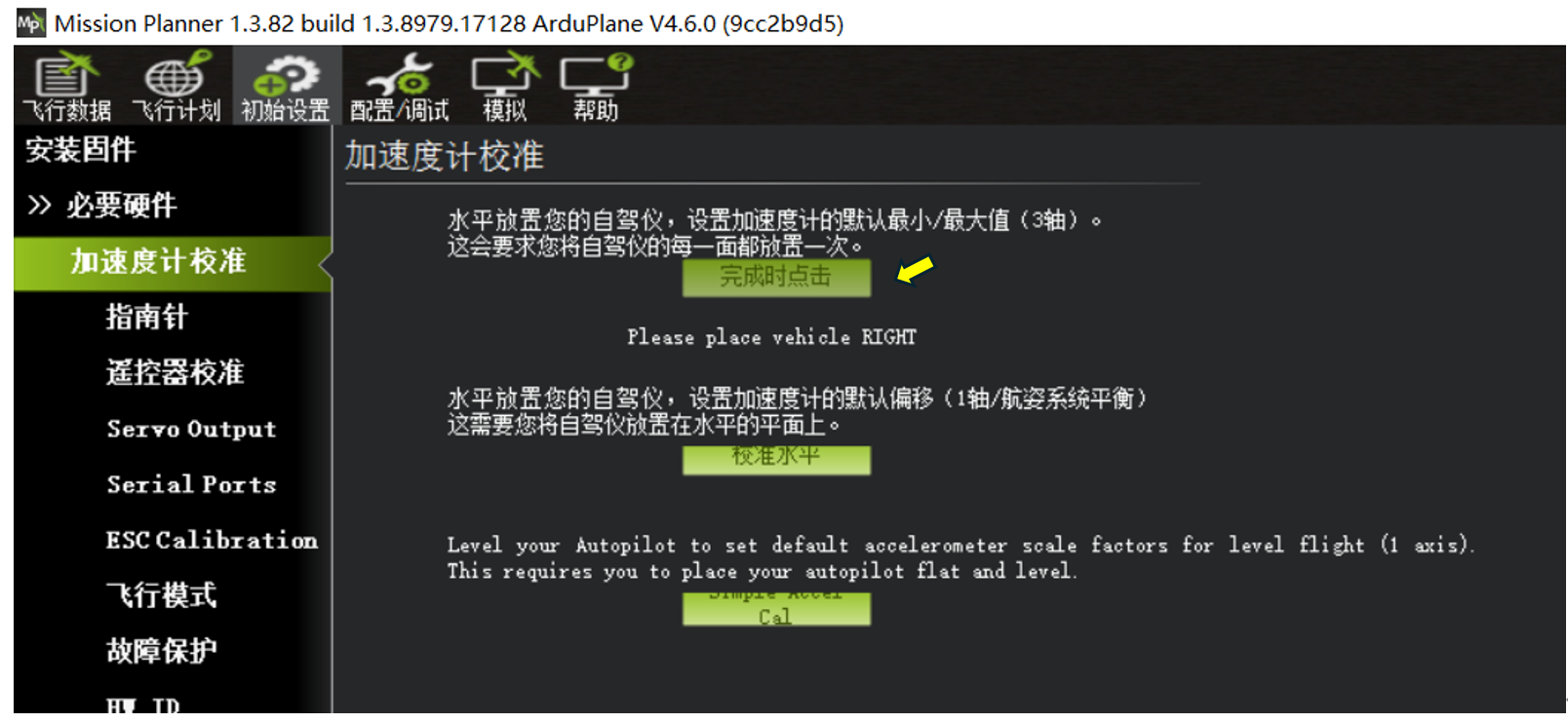
Please place vehicle RIGHT - accelerometer calibration with the right side facing down.
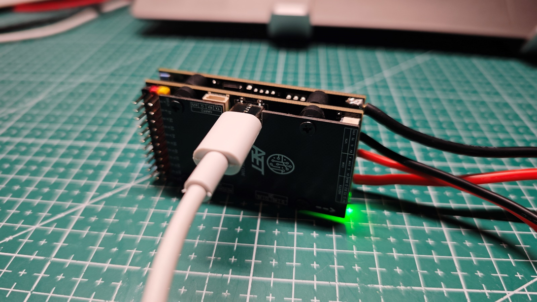
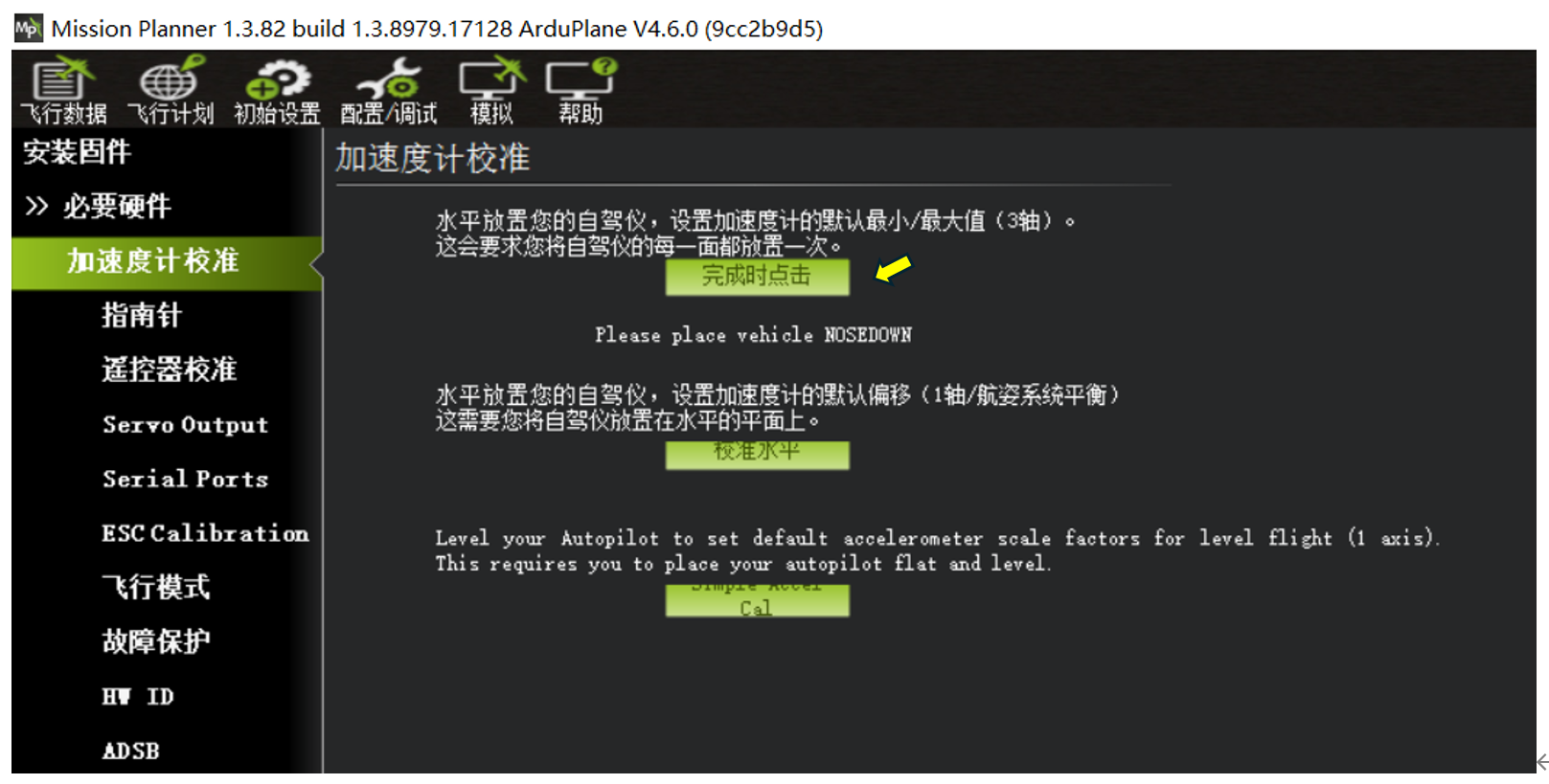
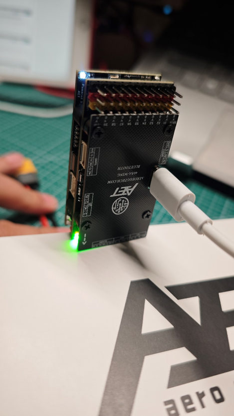
Please place vehicle NOSEDOWN - accelerometer calibration with the front side facing down.
[ ]
(https://doc.aeroeggtech.com/en/uploads/images/gallery/2025-10/image-1759472720499.png)
]
(https://doc.aeroeggtech.com/en/uploads/images/gallery/2025-10/image-1759472720499.png)
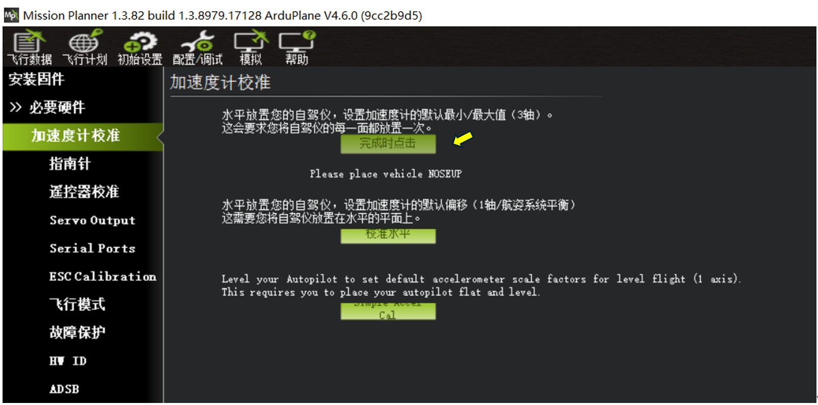
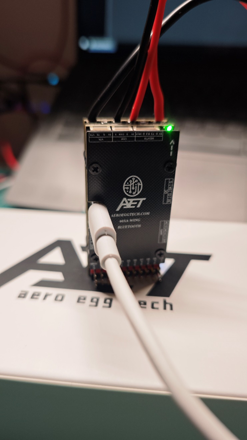
Please place vehicle NOSEUP - accelerometer calibration with the rear side facing down.
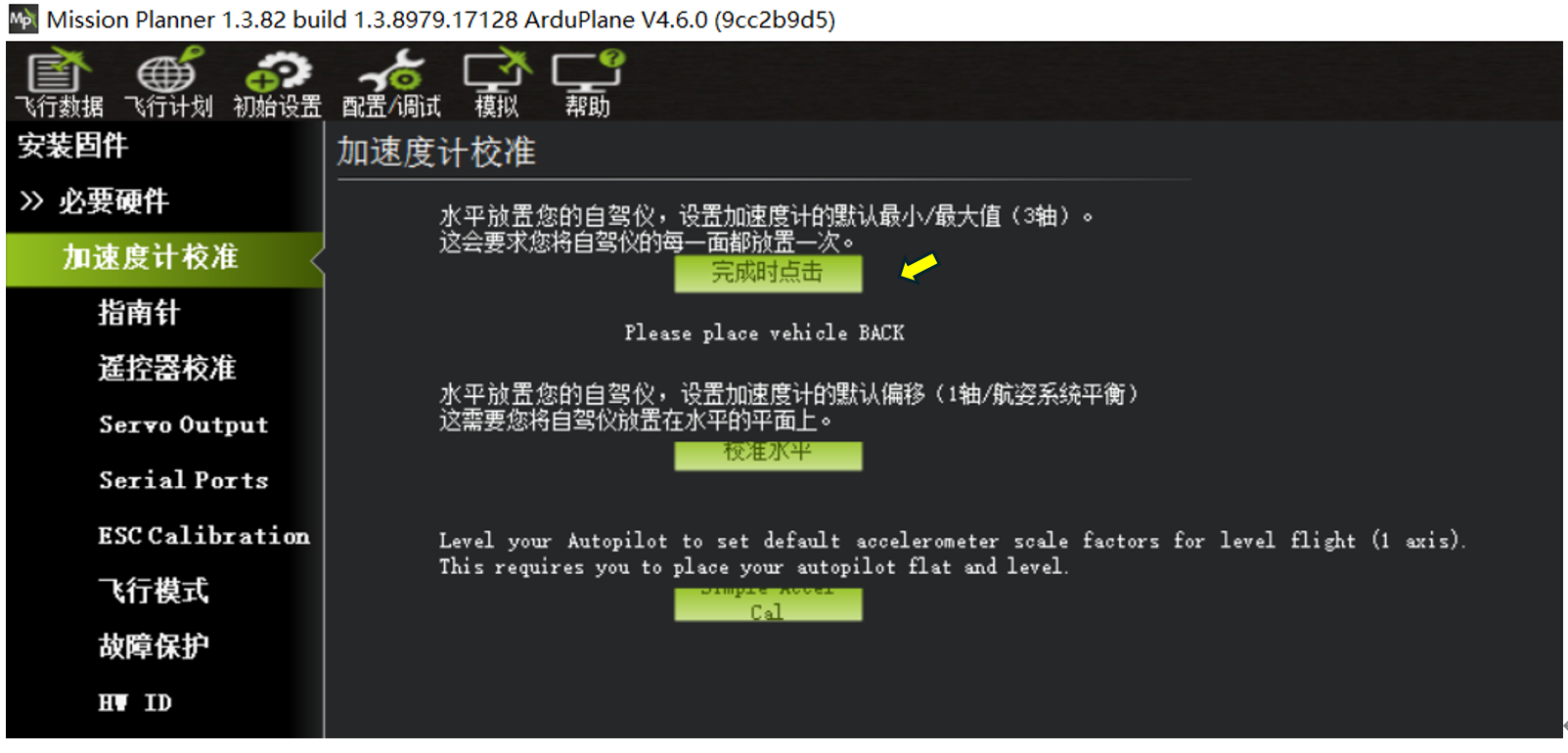
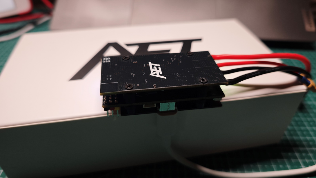
Please place vehicle BACK - accelerometer calibration with the top side facing down.
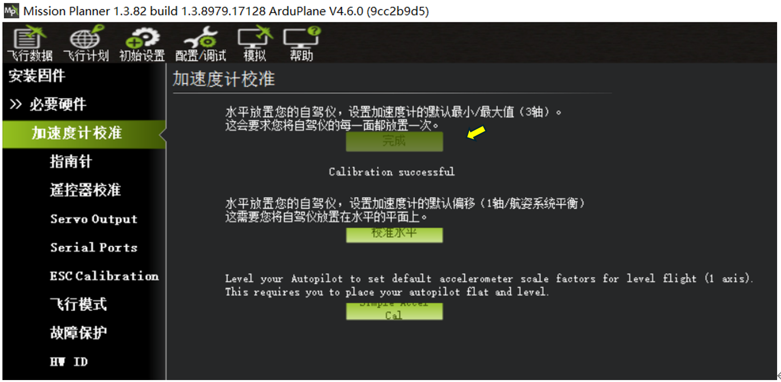 Calibration complete.
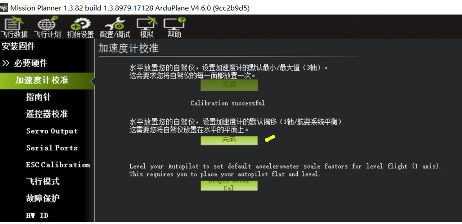
After installing the flight controller, place the aircraft on a level surface and run Level Calibration once.
Section 3: Compass Setup
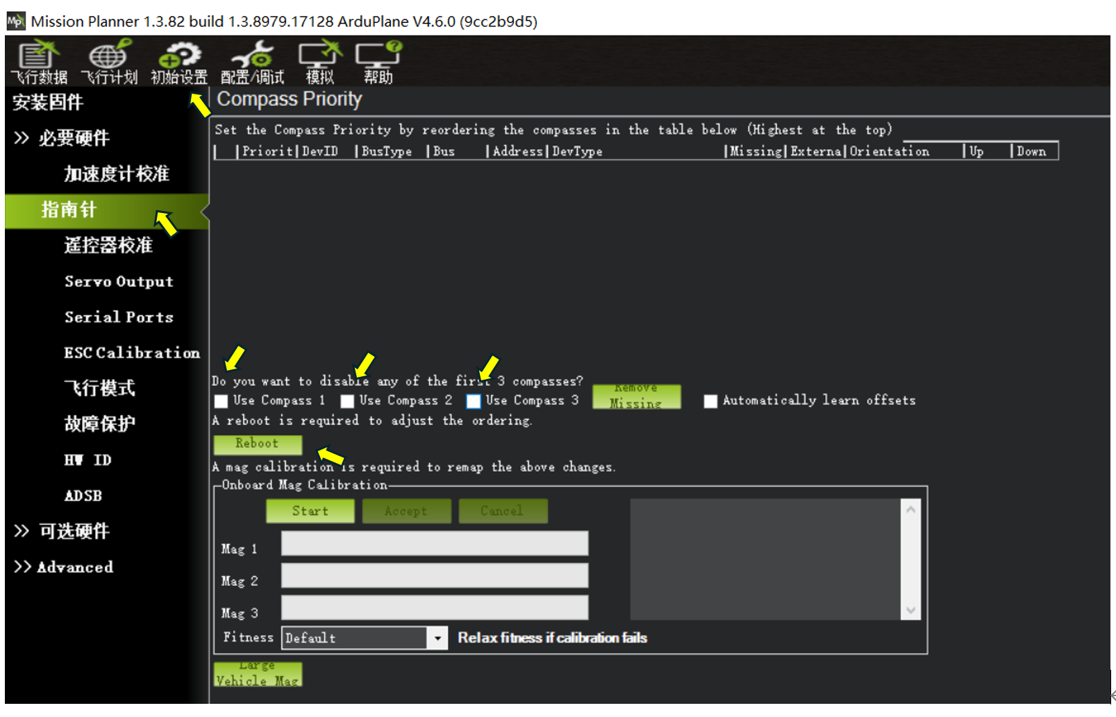
A compass (electronic compass) is not required for basic fixed-wing operation.
You can disable the compass options enabled by default on the flight controller.
On the Initial Setup → Compass page:
Clear the following options: Use Compass1, Use Compass2, and Use Compass3.
Click Reboot to restart the flight controller.
Section 4: Custom Servo and ESC Configuration in Servo Outputs
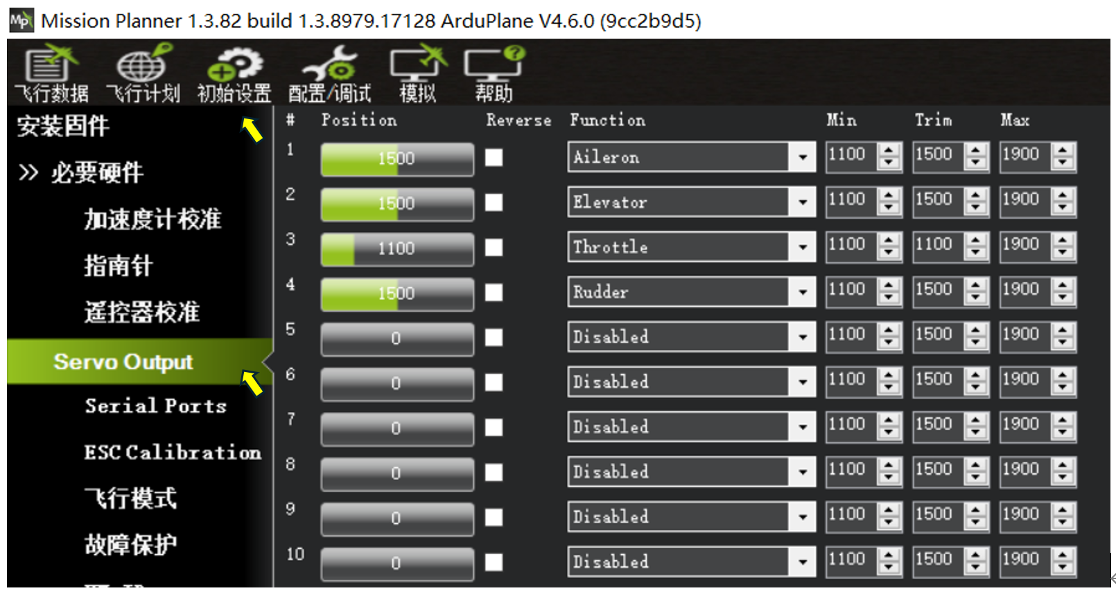
Ardupilot firmware supports fully customizable assignments for flight controller outputs S1–S10.
In the image above, #1 corresponds to flight controller S1, #2 corresponds to S2, and so on.
The default parameters use the conventional AETR layout shown above.
Aileron: aileron servo for roll control
Elevator: elevator servo for pitch control
Throttle: ESC throttle signal
Rudder: rudder servo for yaw control
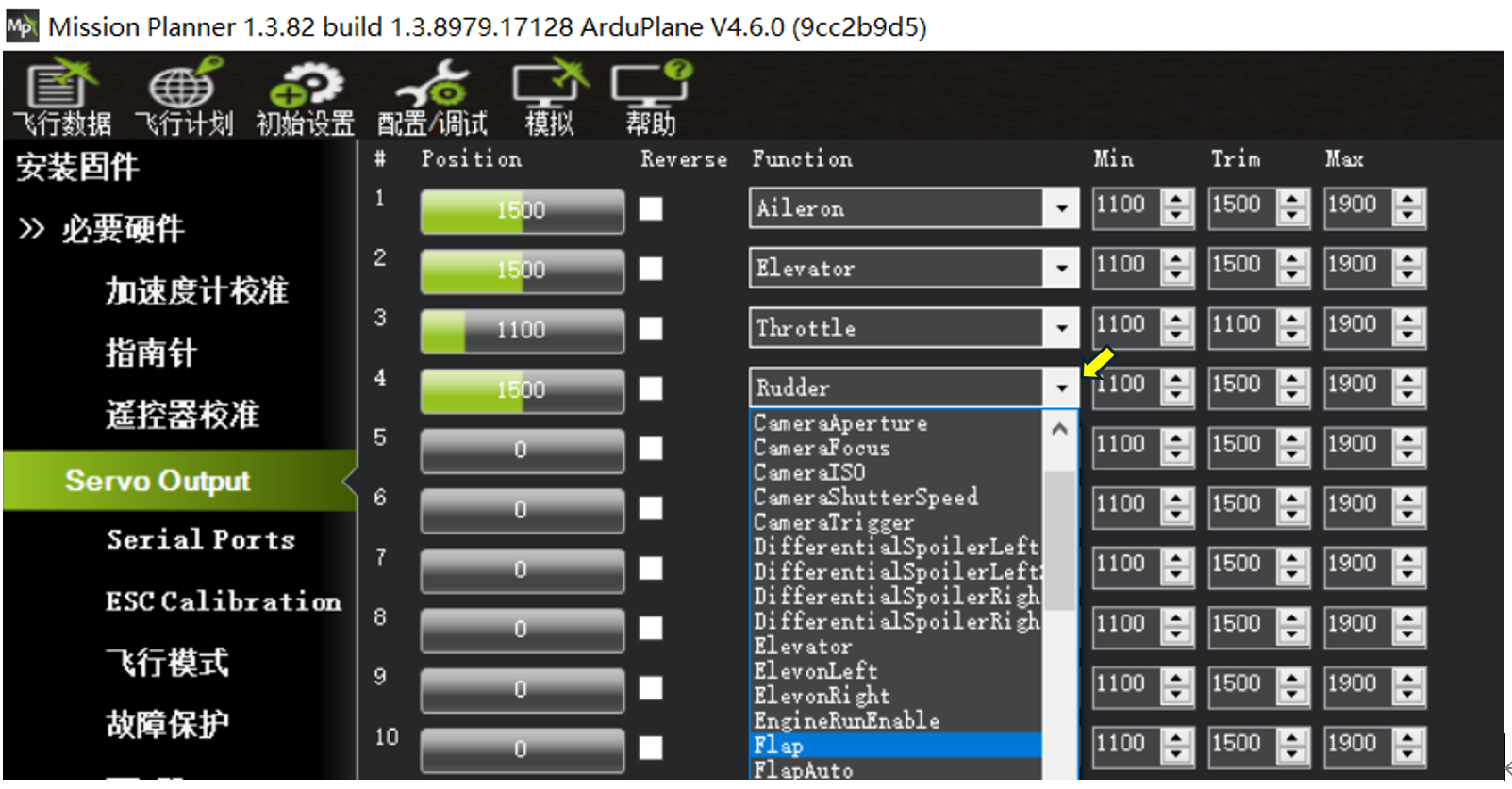
Each Servo output channel can be assigned from its corresponding drop-down menu. This flexibility is one of the key features of Ardupilot firmware. After changing a custom Servo assignment, restart the flight controller for the change to take effect. Common assignment types include:
Aileron: aileron servo for roll control
Elevator: elevator servo for pitch control
Throttle: ESC throttle signal
Rudder: rudder servo for yaw control
ElevonLeft: left flying-wing servo (combined aileron/elevator control)
ElevonRight: right flying-wing servo (combined aileron/elevator control)
ThrottleLeft: left motor ESC throttle signal for differential thrust
ThrottleRight: right motor ESC throttle signal for differential thrust
VTailLeft: left V-tail servo (combined elevator/rudder control)
VTailRight: right V-tail servo (combined elevator/rudder control)
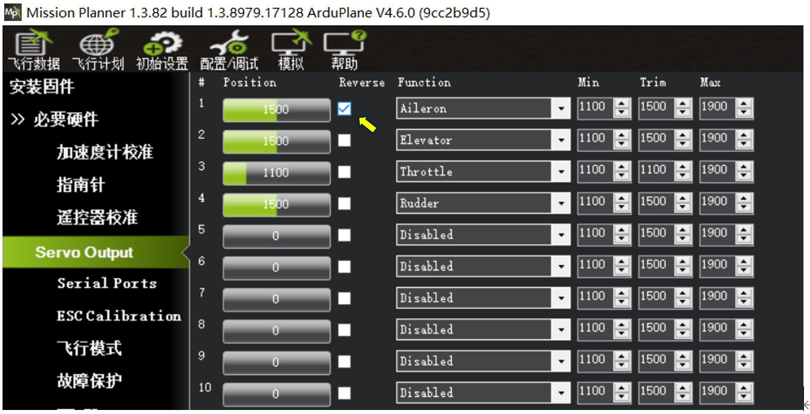
Ardupilot channel outputs update in real time. During later stabilization checks, if a channel moves in the wrong direction when the flight controller corrects aircraft attitude, select “Reverse” for that channel to invert its output.
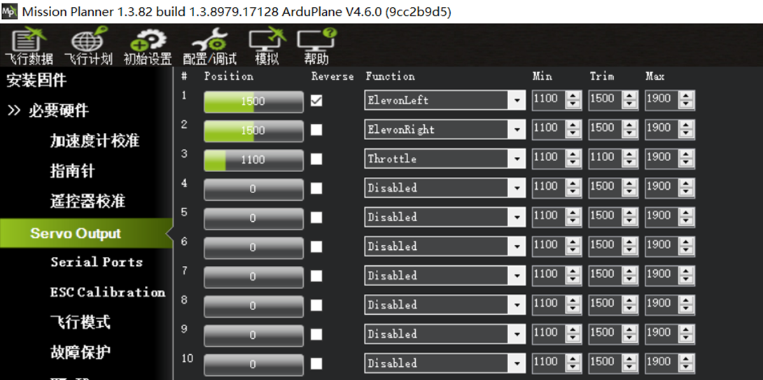
Example 1: For a single-motor pusher flying wing such as ARWING or Freewing, connect the left elevon servo to S1 and set #1 to ElevonLeft. If the servo moves in the wrong direction during setup, select Reverse for #1. Connect the ESC signal wire to S3 and set #3 to Throttle.
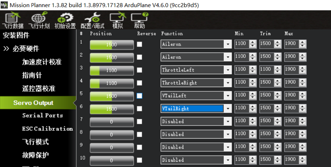
Example 2: For a twin-motor 3D-printed V-tail aircraft using differential thrust, connect the two aileron servos to S1 and S2, and set both #1 and #2 to Aileron. Connect the left-wing ESC signal to S3 and set #3 to ThrottleLeft. Connect the right-wing ESC signal to S4 and set #4 to ThroleLeft. Connect the left V-tail servo to S5 and set #5 to VTailLeft. Connect the right V-tail servo to S6 and set #6 to VTatlRight.
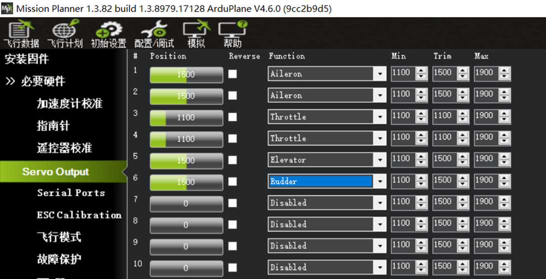
Example 3: For a twin-motor conventional-layout aircraft such as the Great White Shark (Fatty) without differential thrust, connect the two aileron servos to S1 and S2, and set both #1 and #2 to Aileron. Connect the two wing ESC signals to S3 and S4 in either order, and set #3 and #4 to Throttle. Connect the horizontal-tail elevator servo to S5 and set #5 to Elevator. Connect the vertical-tail rudder servo to S6 and set #6 to Rudder.
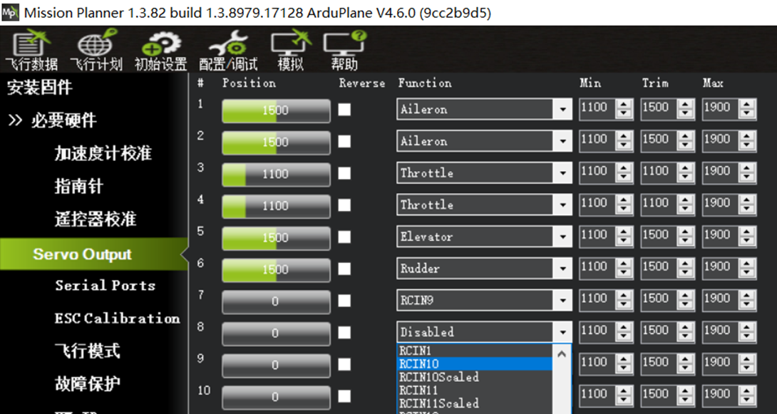
Example 4: To connect a servo gimbal to flight controller S8 for controlling the FPV camera viewing direction, and control that gimbal servo from radio transmitter channel 10 using a custom knob, set #8 to RCIN10.