Chapter 9: OSD Layout Configuration
Configure Video-Link OSD Parameters
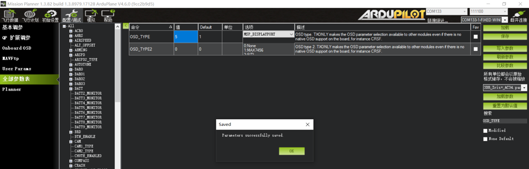
OSD_TYPE This parameter selects the OSD display mode for the video link.
For a standard analog 5.8G video link, keep the default value of 1.
For digital video links using MSP_Displayport, including air units compatible with DJI G2/G3/N3 goggles, Walksnail Avatar air units, and open-source OpenIPC digital HD air units, set this parameter to 5.
For older DJI HD Goggles V1/V2 with a Vista or original dual-antenna air unit, set this parameter to 3.
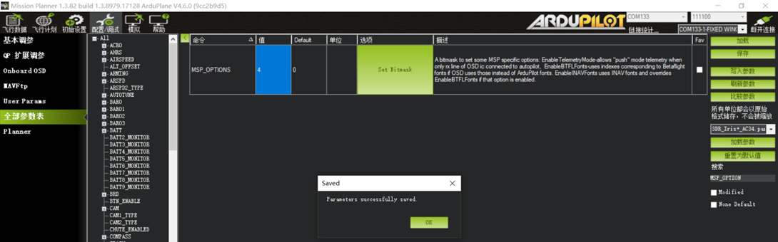
MSP_OPTIONS 4 This parameter must be configured for air units compatible with DJI G2/G3/N3 goggles.
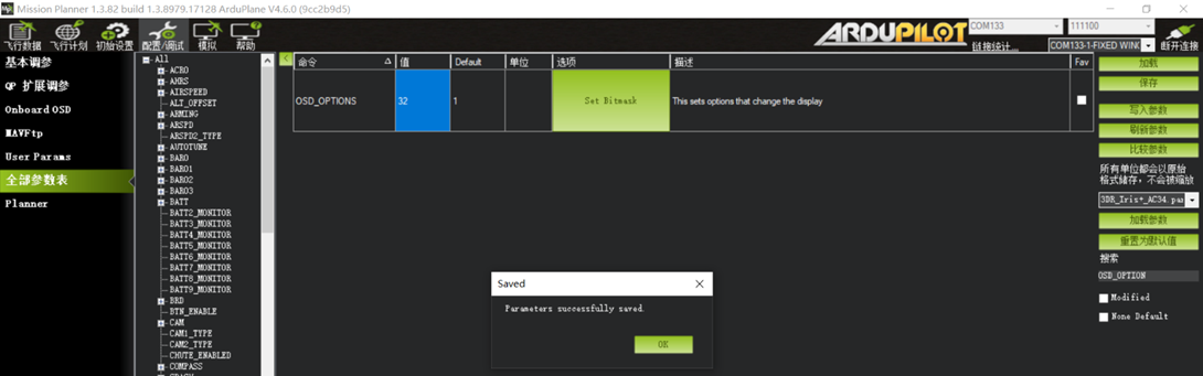
OSD_OPTION 32
This parameter must be configured for air units compatible with DJI G2/G3/N3 goggles.
For an Openipc open-source digital air unit, set this parameter to 42.
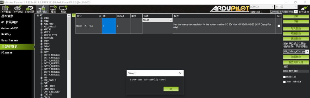
OSD1_TXT_RES 1
This parameter adjusts the OSD layout resolution and is recommended for all HD video links.
Open OSD information settings: Config/Tuning -- Onboard OSD -- Screen1.
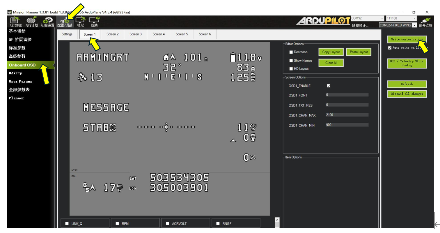
Ardupilot OSD configuration is similar to INAV configuration and tuning because the flight controller contains an integrated OSD module. In the OSD content list at the bottom, select the items to display and drag them to the desired positions. With the flight controller powered and the video link and camera connected, reposition an OSD item and click “Write customization” in the upper-right corner to update its position on the receiving display.
If the default OSD positions do not suit your preferences, drag each item to the desired location. If the OSD item panel at the bottom is too small, enable Reduced View to obtain a wider overview.
For a digital video link, enable HD Layout to obtain a wider layout workspace.
If the computer display resolution is below 1920*1080, the OSD layout workspace may not be fully visible.
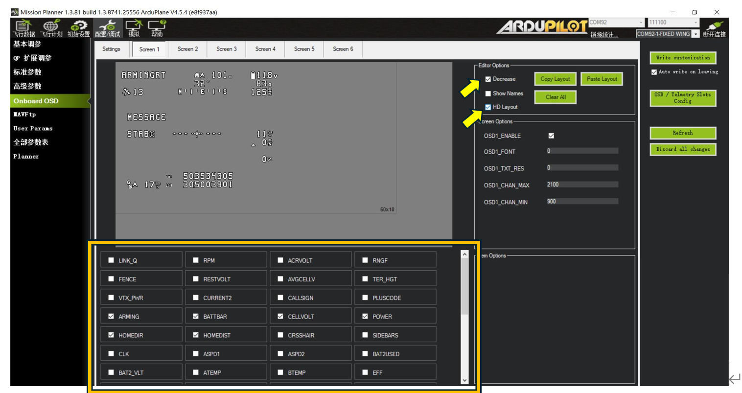
The boxed area in the figure above lists the available OSD items.
Common items are described below:
BAT_VOLT Battery voltage
CELLVOLT Per-cell battery voltage
CURRENT Current
POWER Current system power
BATUSED Battery capacity consumed
RSSI Radio signal strength
SATS GPS satellite count
HDOP GPS positioning accuracy
FLTMODE Current flight mode
MESSAGE System messages
HORIZON Artificial horizon
HOME Distance from home
DIST Flight distance
HEADING Bearing from home
THROTTLE Current throttle value
COMPASS Compass heading
GPSLAT GPS latitude
GPSLONG GPS longitude
ROLL Current roll angle
PITCH Current pitch angle
ALTITUDE Current relative altitude
GSPEED Current GPS ground speed
VSPEED Current vertical speed m/S
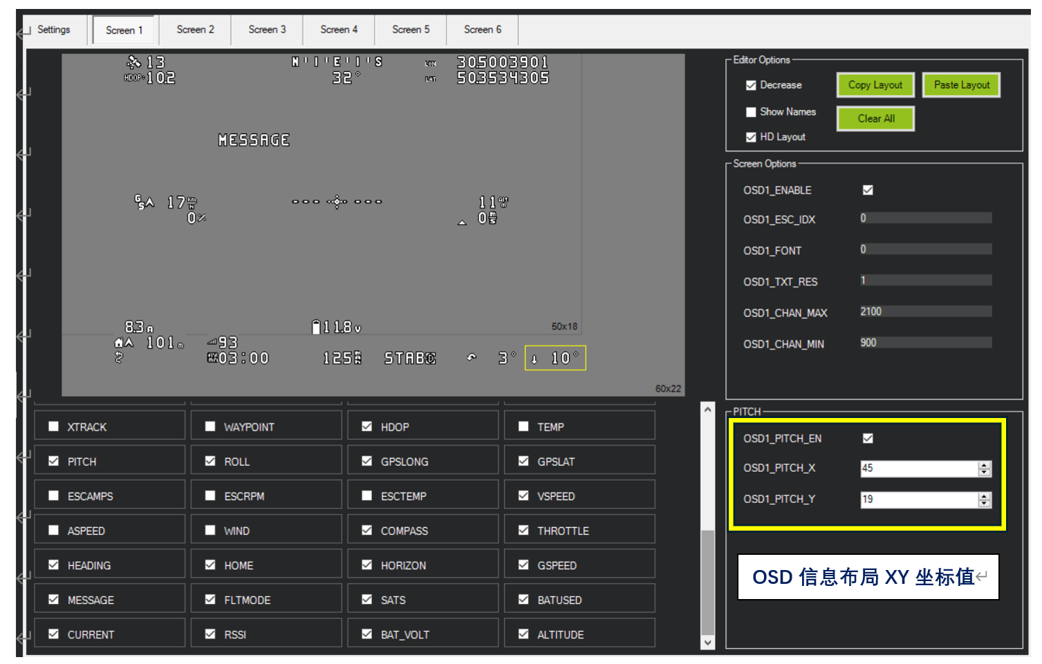
For DJI G2, G3, and N3 video goggles, the following OSD layout is recommended.
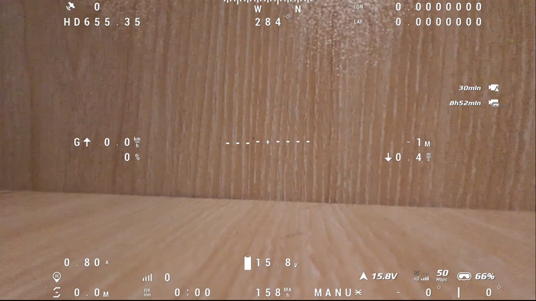
The corresponding OSD layout appears in the goggles as follows:
The OSD items and XY coordinates shown above are listed below. Select each OSD item and modify its XY coordinates until the layout matches your preferences.
FLTIME Armed flight time 14 19
DIST Flight distance 5 19
HDOP Positioning accuracy 6 1
PITCH Pitch value 45 19
ROLL Roll value 39 19
GPSLONG GPS longitude 35 0
GPSLAT GPS latitude 35 1
VSPEED Current vertical speed 38 10
COMPASS Compass heading 26 0
THROTTLE Current throttle value 10 10
HEADING Bearing from home 25 1
HOME Distance from home 5 18
HORIZON Artificial horizon 26 9
GSPEED Current ground speed 7 9
MESSAGE System messages 15 5
FLTMODE Current mode 31 19
SATS GPS satellite count 6 0
BATUSED Battery capacity consumed 24 19
CURRENT Current 6 17
RSSI Radio signal strength 14 18
BAT_VOLT Battery voltage 24 17
ALTITUDE Current altitude 38 9
DJI V1 and V2 goggles do not support certain OSD items. Set the serial port to DJI FPV.
Common items known to be supported include: battery voltage, current, battery capacity, GPS satellite count, latitude and longitude, distance from home, altitude, vertical speed, speed, RSSI, pitch angle, and roll angle.
Items confirmed as unsupported include: artificial horizon, accumulated flight distance, bearing from home, mode name, and current throttle value.
When using a DJI HD air unit with V1 or V2 HD goggles, confirm that the air unit is powered, the goggles are connected, and “Custom OSD” is enabled in the DJI goggles. The goggles can then display their supported OSD item types.
DJI Digital Video Link (V1/V2 Goggles) OSD Reference, Including XY Coordinates:
HOMEDIR Home-direction arrow 15 13
HOMEDIST Distance from home 2 13
CRSSHAIR Crosshair 14 8
PITCH Pitch angle 19 14
ROLL Roll angle 19 13
GPSLONG Longitude 0 0
GPSLAT Latitude 0 1
VSPEED Vertical speed 23 8
GSPEED GPS speed 4 7
MESSAGE Flight mode 1 14
SATS GPS satellite count 8 14
BATUSED Battery capacity consumed 13 14
CURRENT Current 4 8
RSSI Current radio signal strength 9 13
BAT_VOLT Battery voltage 13 13
ALTITUDE Altitude 21 7