Chapter 4: Receiver, GPS, Video Link, Bluetooth, and Telemetry Configuration
Receiver configuration:
When using an SBUS receiver (such as Tiandifei WBUS, RadioLink, or Futaba series receivers), connect it directly to the flight controller SBUS port with a 2.54 mm 3-pin Dupont connector. The SBUS port corresponds to SERIAL PORT2 (UART2). The default setting 57600 RCIN automatically detects the SBUS receiver signal.
When using an ELRS/CRSF receiver, connect it to UART2 on the side of the flight controller using the SH1.0 4P connector (see the wiring diagram on page 10 of this guide). These receivers are normally configured as 115200 RCIN. The flight controller firmware no longer supports PPM or PWM receivers.
GPS module configuration:
Connect the GPS to UART5 on the side of the flight controller using the SH1.0 6P connector (see the wiring diagram on page 11 of this guide). Most GPS modules are configured as 38400 GPS.
Some GPS modules support a Speed baud rate of 115200.
Verifying the GPS module connection
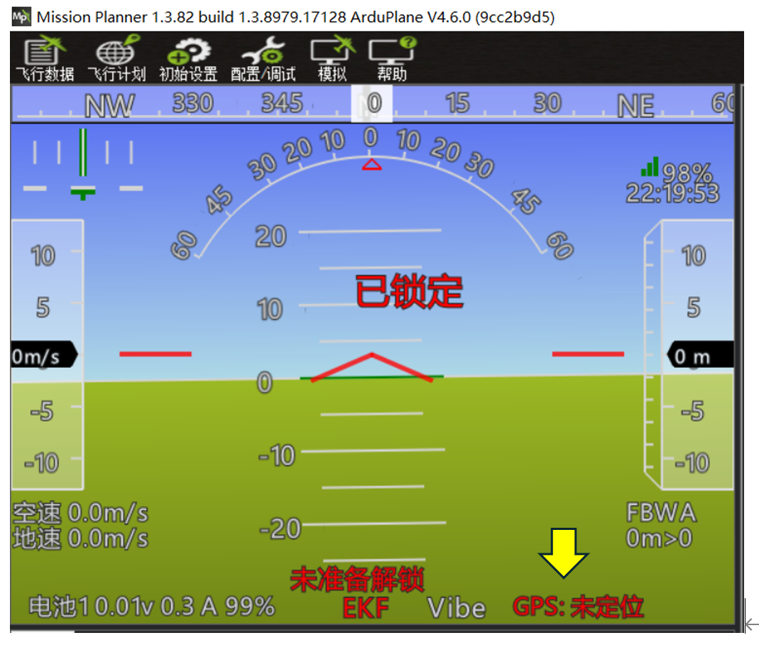
When the GPS wiring and serial-port settings are correct and the module is operating normally, the lower-right corner of the attitude display on the ground station home page shows the GPS state.
Before a position fix is acquired, "GPS: No Fix" is displayed in red. After acquiring satellites and a position fix outdoors, "GPS: 3D Fix" is displayed in white.
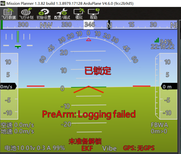
If the GPS wiring or serial-port settings are incorrect, or the GPS has a compatibility or hardware fault, the flight controller cannot detect it. The lower-right corner of the attitude display then shows "GPS: No GPS" in red.
Digital video air unit configuration:
Connect the digital video air unit to the HDVTX connector on the front of the flight controller using the SH1.0 6P connector. This connector corresponds to UART3 (see the wiring diagram on page 12 of this guide). Digital air units are normally configured as 115200 DispiayPort.
This includes DJI air units compatible with DJI G2, G3, and N3 goggles, Caddx Avatar series air units, and open-source OpenIPC HD video systems.
For legacy DJI air units and Vista used with DJI V1 or V2 goggles, set the UART3 Protcol value to DJI FPV.
Onboard Bluetooth telemetry module configuration
The onboard Bluetooth telemetry module on the AET F405A WING flight controller is connected internally to UART6.
Configure this port as 115200 Mavlink2.
External telemetry module configuration
Connect an external telemetry module to the TX1 and RX1 solder pads on the rear of the flight controller; these pads correspond to UART1.
A typical telemetry link is configured as 115200 Mavlink2.
Recommended port assignments for common peripherals are shown below.
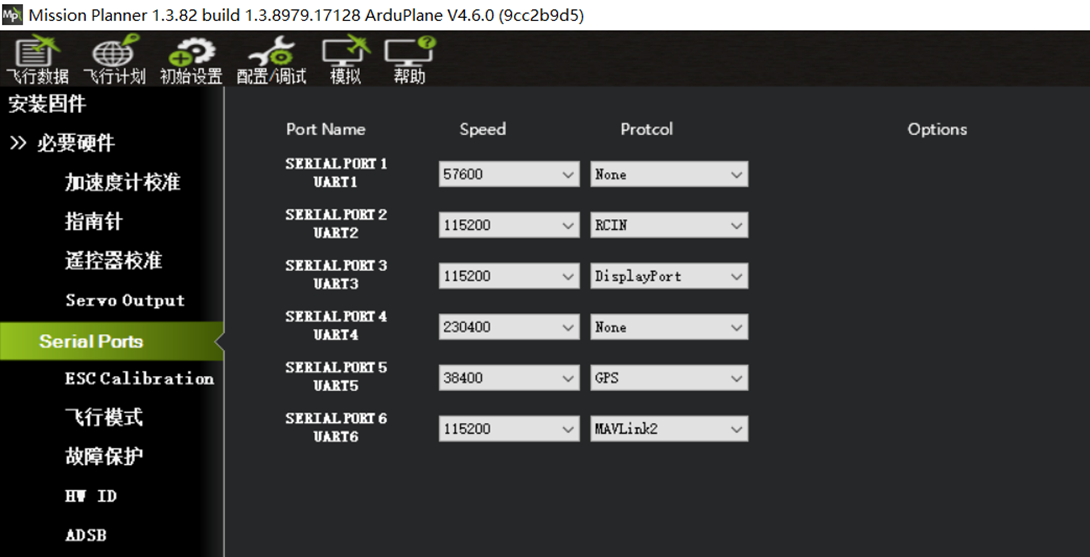
Connect the ELRS receiver to UART2.
Connect the digital HD air unit to UART3.
Connect the GPS module to UART5.
Reserve UART6 for the onboard Bluetooth telemetry module.
After configuring and wiring all serial peripherals correctly, the receiver and GPS module should be connected and configured. Use the following steps to verify that radio control input reaches the flight controller through the receiver and that the GPS module is operating correctly.