Chapter 6: Flight Controller Orientation and Attitude Display Check
The attitude indicator in ArduPilot firmware represents the pilot's first-person view from inside the cockpit, not an external third-person view.
The blue upper area represents the sky, the green lower area represents the ground, and the boundary between them is the horizon.
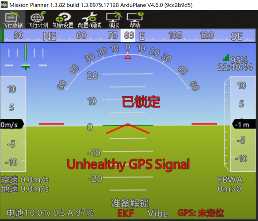
The aircraft or flight controller is level in this example. The standard physical inspection view is from directly behind the aircraft.
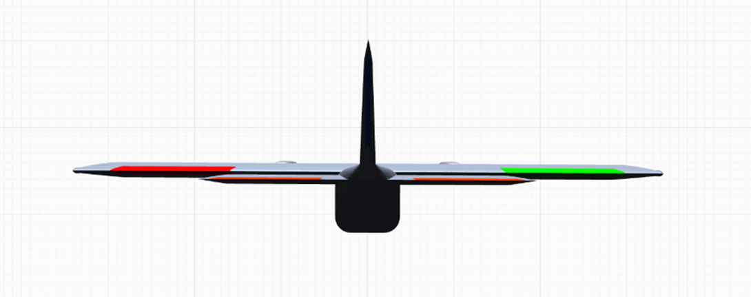
When the aircraft or flight controller pitches nose-up, more blue sky and less green ground are displayed. The attitude indicator should appear as follows:
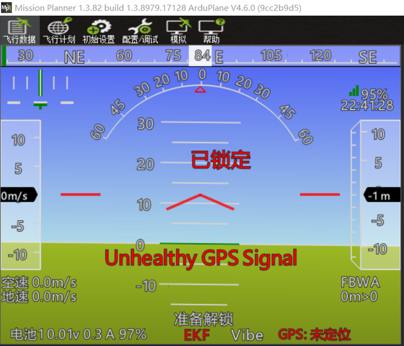
The corresponding aircraft attitude should be:
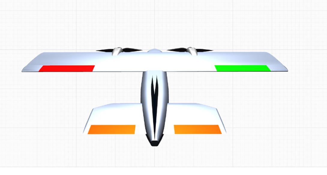
When the aircraft or flight controller pitches nose-down, less blue sky and more green ground are displayed. The attitude indicator should appear as follows:
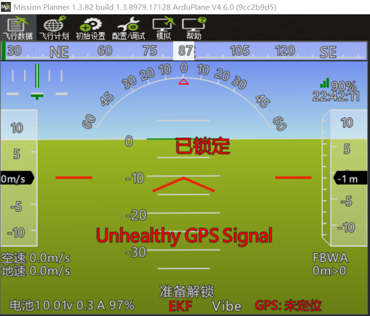
The corresponding aircraft attitude should be:
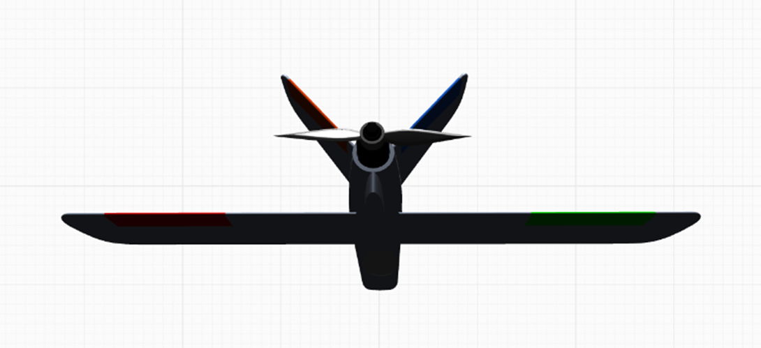
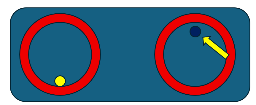
When the aircraft or flight controller banks left, visualize the view from the cockpit as the aircraft banks left and note how the sky and horizon move across the windshield. The correct attitude indication is shown below:
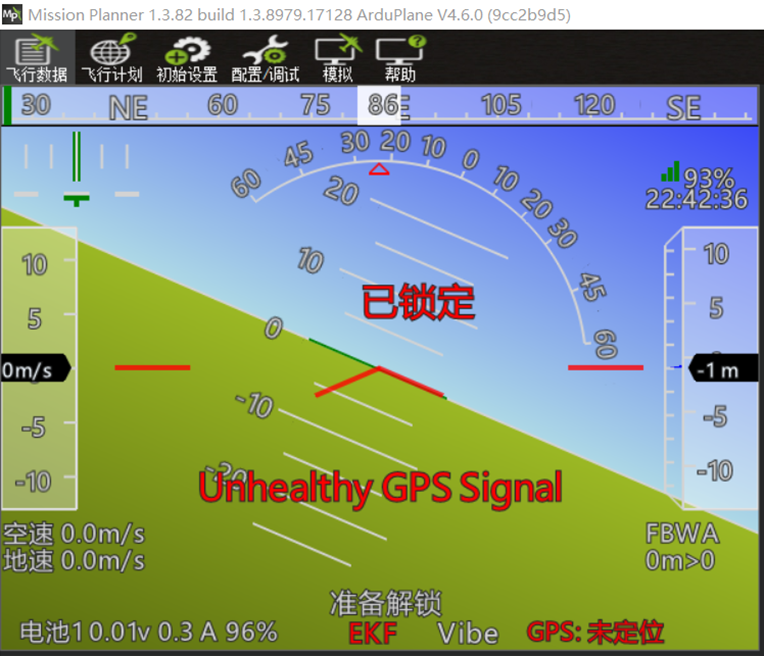
The aircraft should appear as follows from an external view:
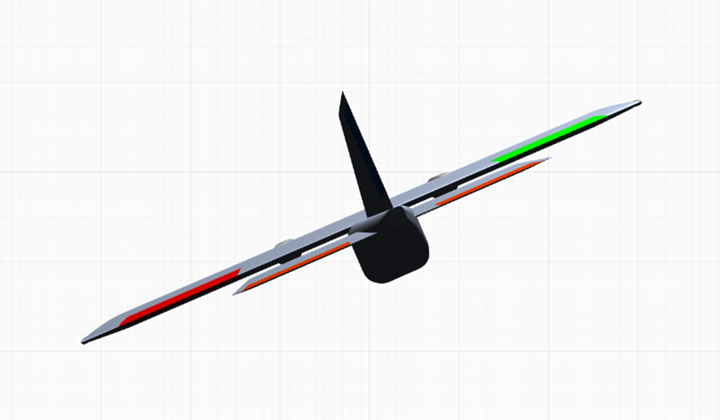
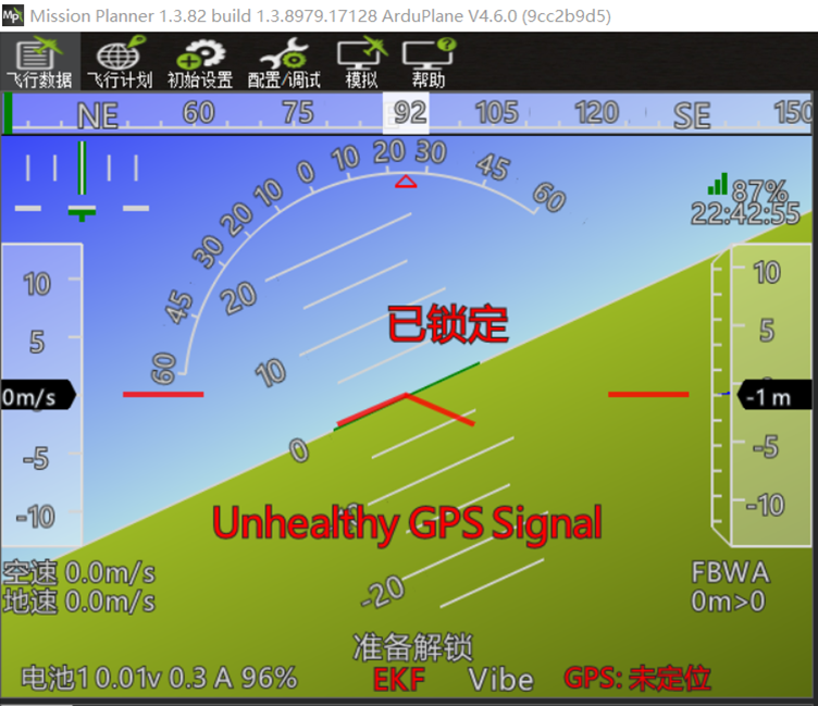
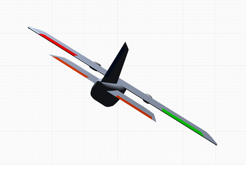
When the aircraft or flight controller banks right, visualize the view from the cockpit as the aircraft banks right and note how the sky and horizon move across the windshield. The correct attitude indication is shown below:
The aircraft should appear as follows from an external view:
Stabilization Control-Surface Feedback and Radio Stick-Input Checks
Perform these checks only after the flight controller and servos have been installed in the airframe and all control surfaces have been connected to their servos.
Radio Transmitter Stick Modes
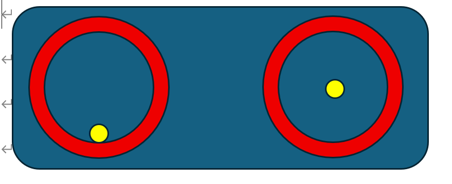
Left-hand throttle (Mode 2 / American mode)
The left stick controls throttle vertically and yaw horizontally.
The right stick controls pitch vertically and roll horizontally.
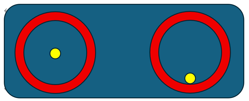
Right-hand throttle (Mode 1 / Japanese mode)
The left stick controls pitch vertically and yaw horizontally.
The right stick controls throttle vertically and roll horizontally.
Stabilized-Mode Control-Surface Correction Direction Check (Very Important)
Switch the flight controller to FBWA stabilized mode for this check.
For Mode 2, set the left stick fully down and centered horizontally, and center the right stick.
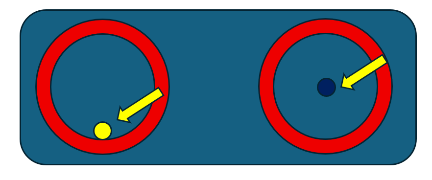
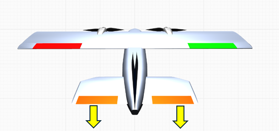
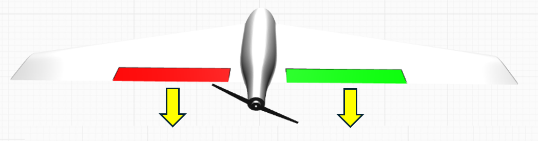
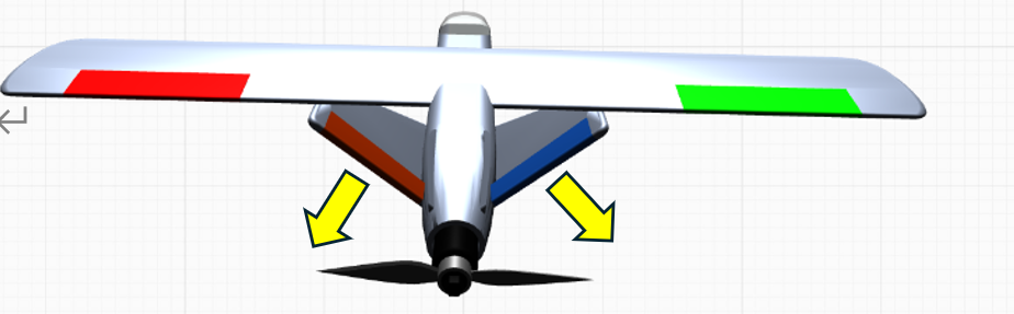
Lift the aircraft and move it through the attitudes shown below. Verify that the control surfaces produce the illustrated corrective responses.
Conventional-layout aircraft pitched nose-up
Flying-wing aircraft pitched nose-up
V-tail aircraft pitched nose-up
Conventional-layout aircraft pitched nose-down
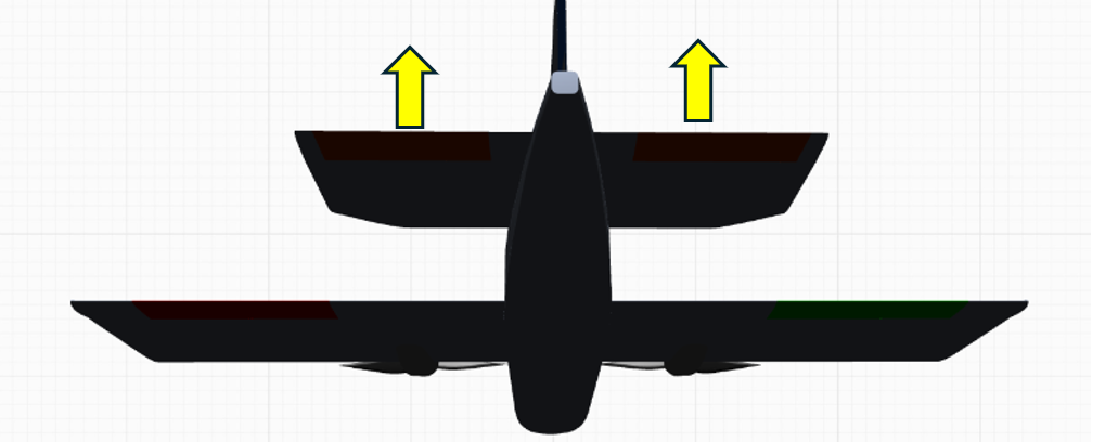
Flying-wing aircraft pitched nose-down
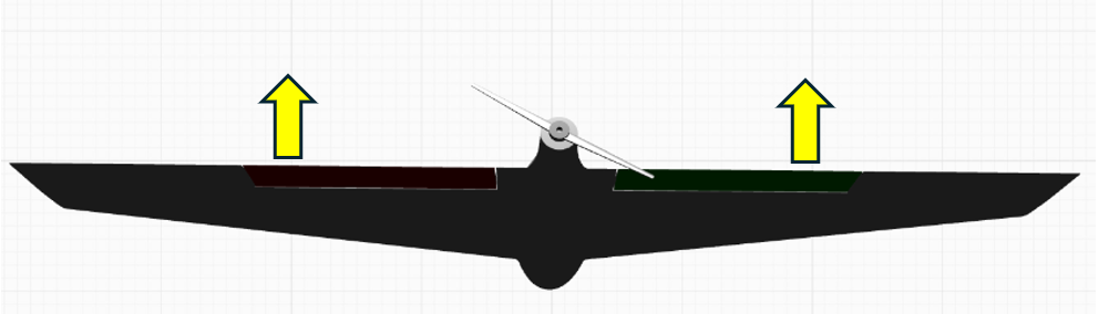
V-tail aircraft pitched nose-down
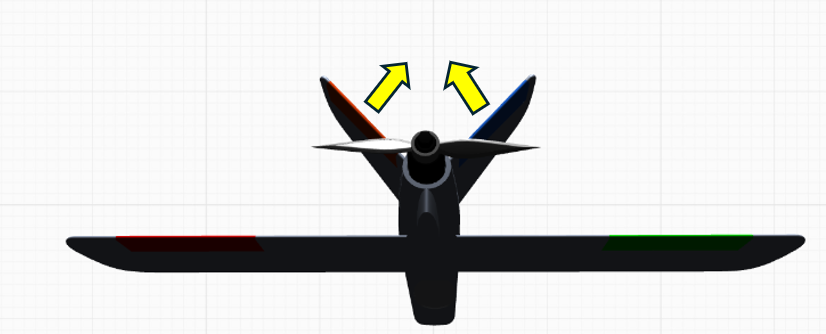
Conventional-layout aircraft banking left
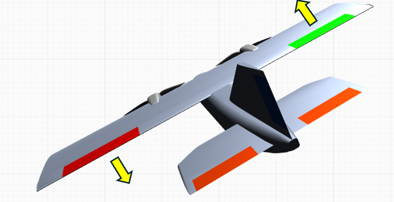
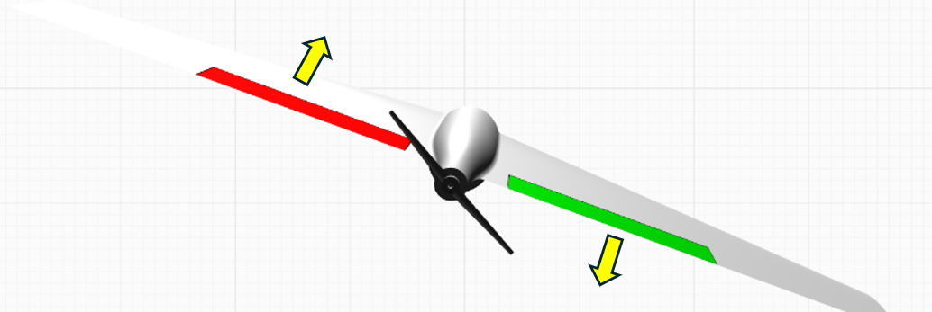
Flying-wing aircraft banking left
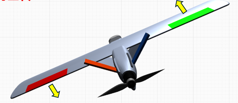
V-tail aircraft banking left
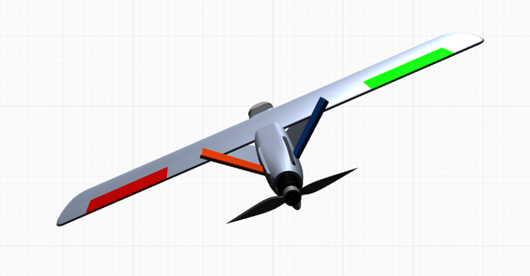
Conventional-layout aircraft banking right
Flying-wing aircraft banking right
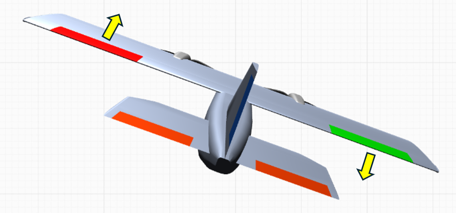
V-tail aircraft banking right
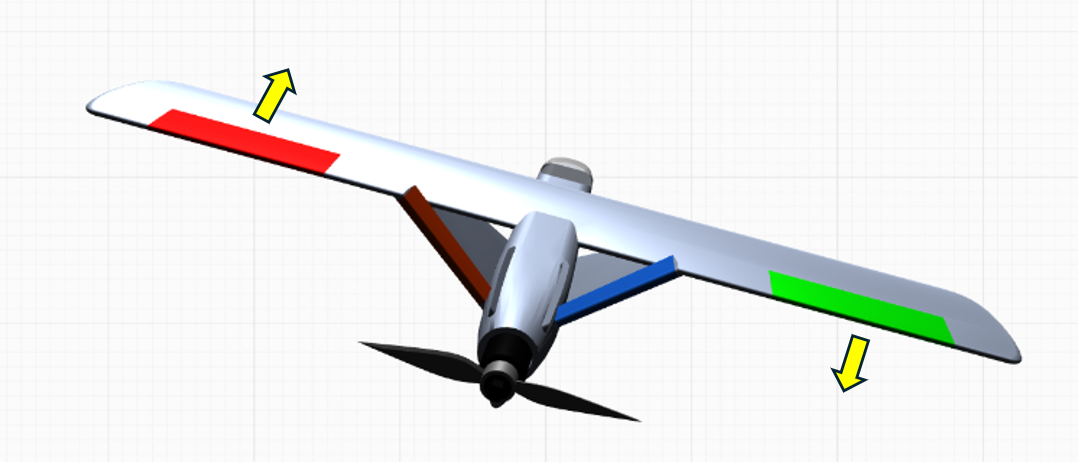
If a stabilization correction moves a control surface in the wrong direction, open the ground station Servo Output page and enable Reverse for the corresponding channel. Continue until every control surface corrects in the proper direction.
For the radio stick-input control-surface check, switch the flight controller to Manual mode.
Move the right stick fully down.
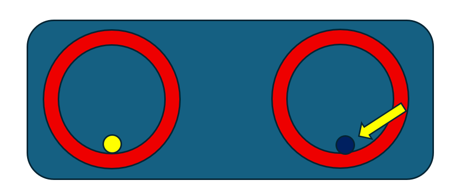
The aircraft control surfaces should respond as follows:
Conventional layout
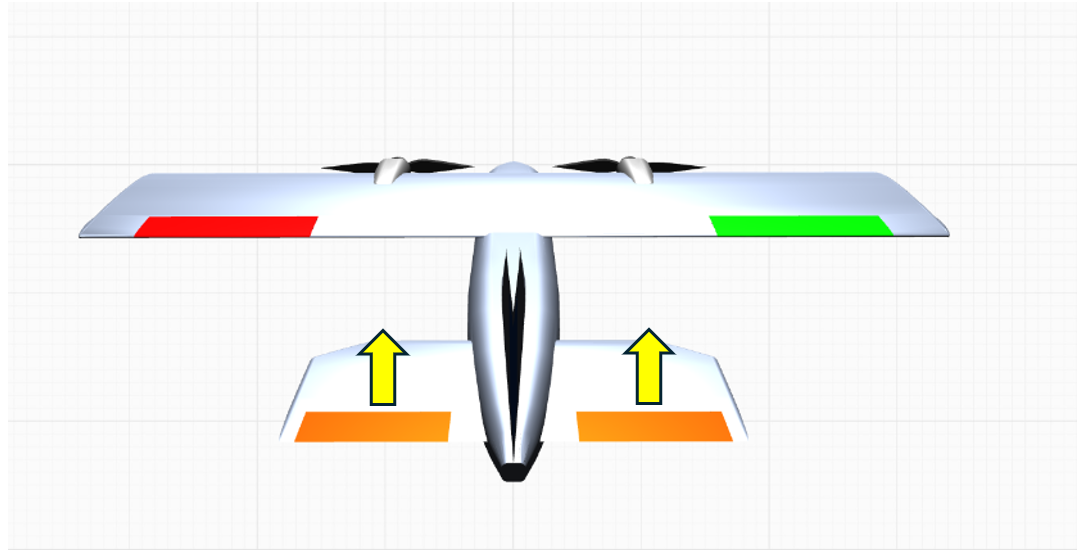 Flying-wing layout
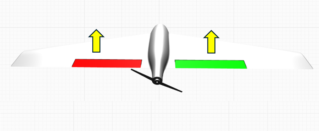 V-tail layout
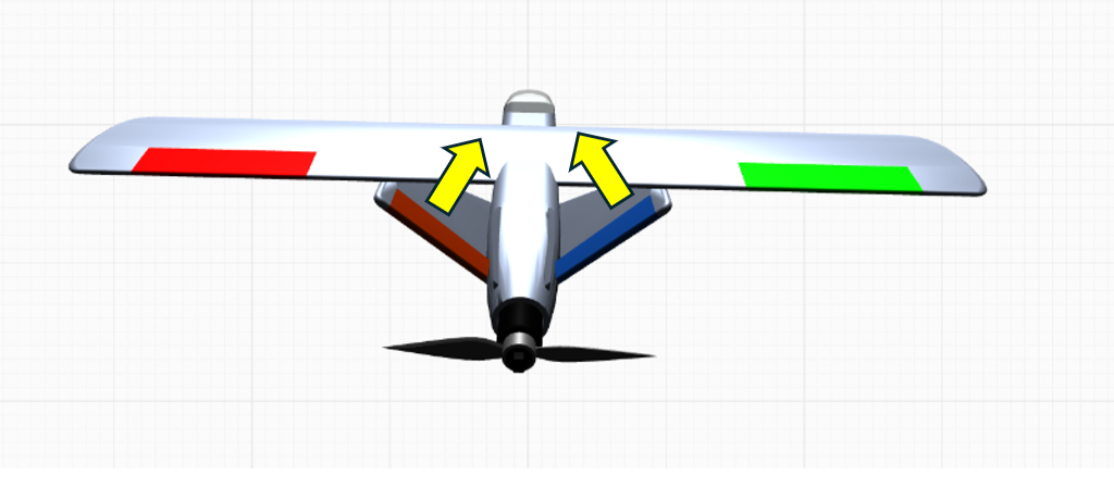
Move the right stick fully up.
The aircraft control surfaces should respond as follows:
Conventional layout
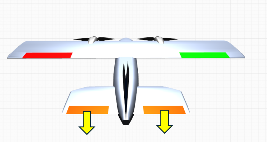 Flying-wing layout
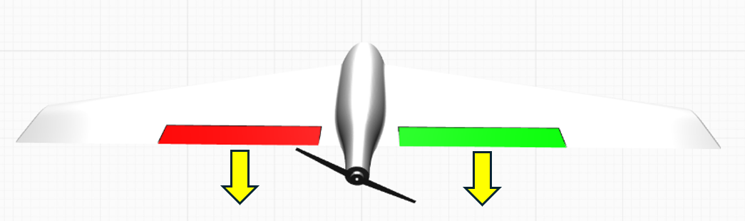 V-tail layout
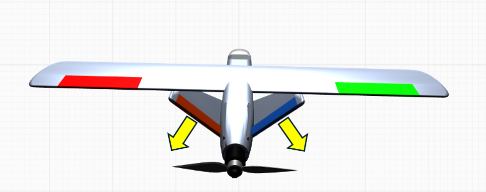
Move the right stick fully left.
The aircraft control surfaces should respond as follows:
Conventional layout
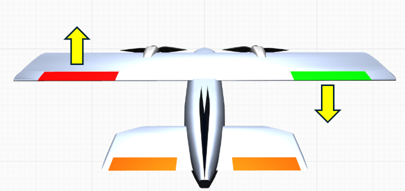 Flying-wing layout
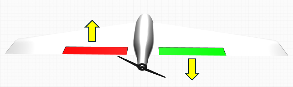 V-tail layout
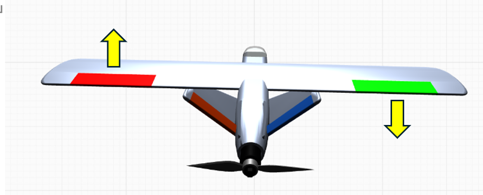
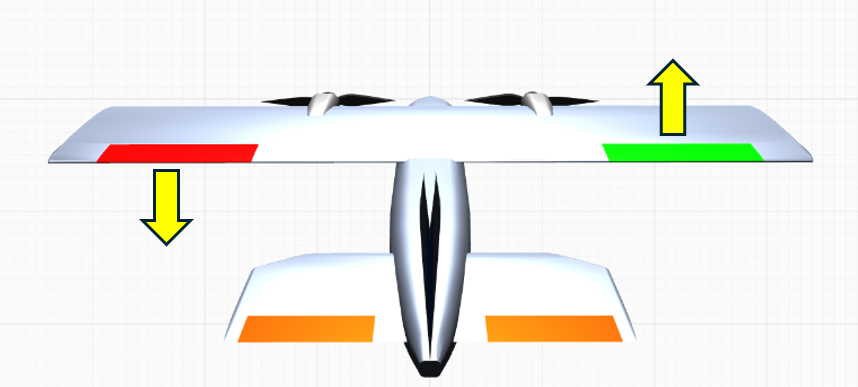
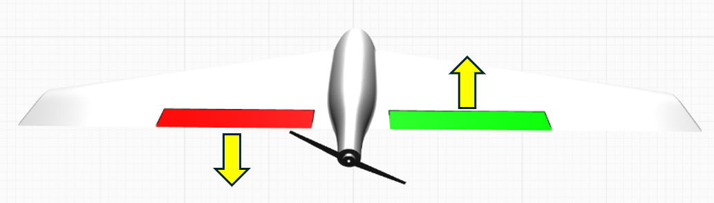
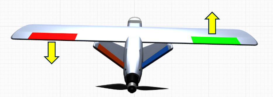
Move the right stick fully right.
The aircraft control surfaces should respond as follows:
Conventional layout
 Flying-wing layout
 V-tail layout
 If a control surface moves in the wrong direction in Manual mode, open Radio Calibration, select the corresponding stick channel, and enable Reverse for that channel. See page 37 for details.