Full Parameter List
Most additional parameters are configured individually in the Full Parameter List. This level of detailed control is a key feature of ArduPilot firmware.
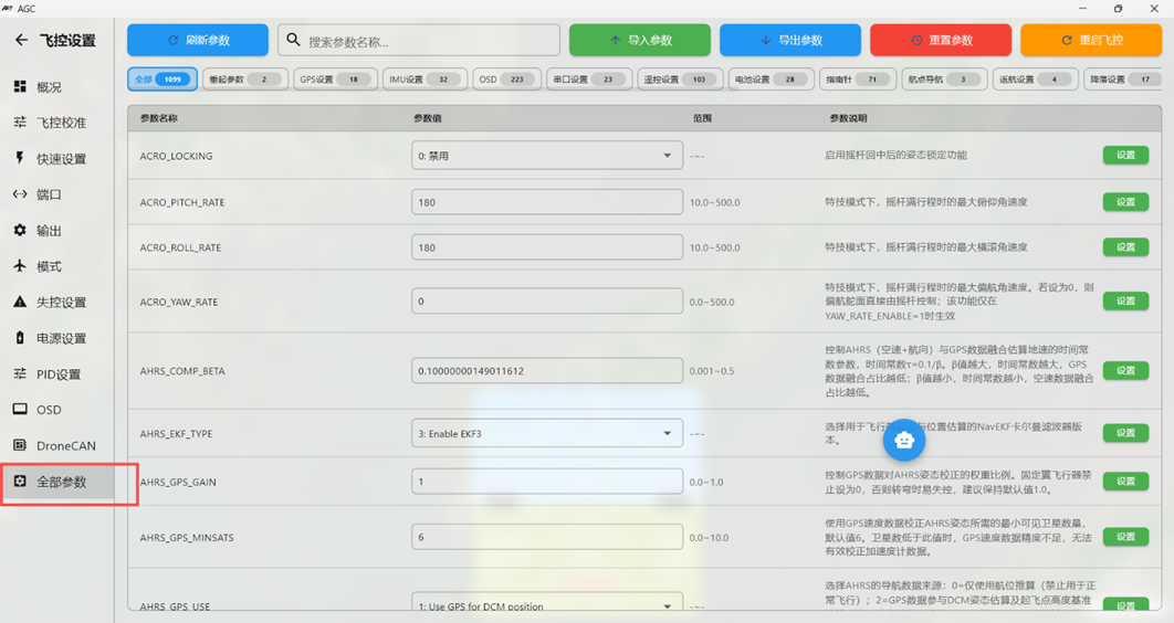
When using the Full Parameter List, keep the configuration reference TXT file open on the computer for comparison.
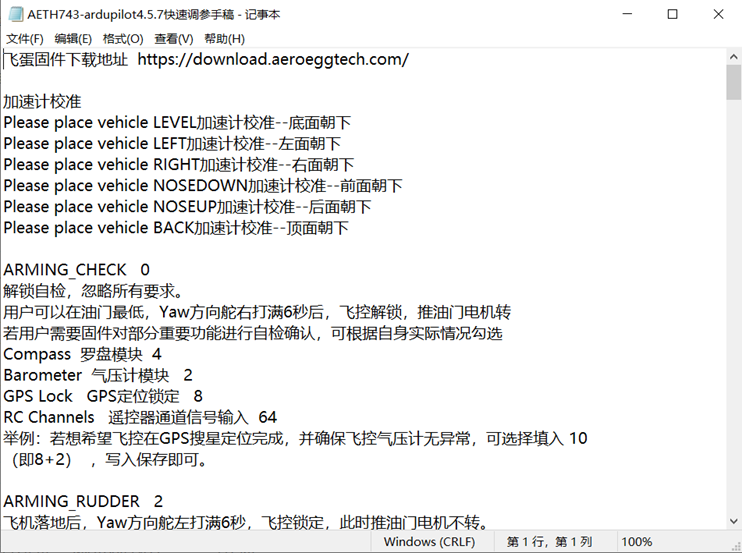
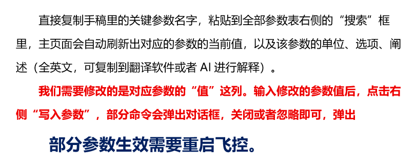
6.1. Enable the Safety Switch
Brd_Safety_Deflt
Configure the safety switch. This is generally set to 0 (not used). Note: the safety switch is not the same as arming.
6.2. Pre-Arm Checks and Arming
ArduPilot firmware applies strict arming requirements. With default parameters, dozens of pre-arm checks must pass before arming is allowed. Search for ARMING parameters.
This defines the list of required systems, similar to a camping checklist that requires a tent, flashlight, and map. 。 ARMING_REQUIRE defaults to 1; change it to 45. 1 (radio transmitter) + 4 (compass) + 8 (GPS data) + 32 (airspeed) = 45. Set it to 0 to disable pre-arm checks and ignore all requirements. This is generally used only during bench testing. Barometer, Compass, GPS Lock (valid 3D fix), RC Channels, Board voltage, Battery level, Airspeed sensor, Logging Available, Hardware safety switch, and GPS Configuration (precision positioning information)
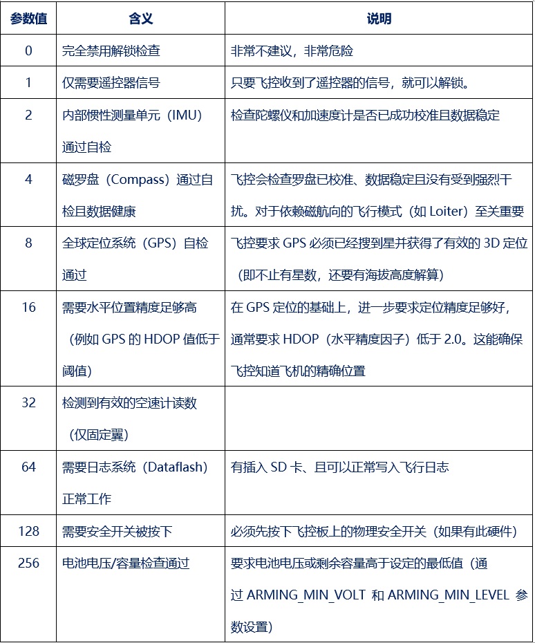 This defines the inspection criteria for each required system, similar to checking whether the tent is damaged, the flashlight works, and the map is current.
ARMING_CHECK defaults to 1, which checks all configured system requirements. Setting it to 0 disables the checks; this is hazardous and should generally be used only for testing. Use it with ARMING_REQUIRE: ARMING_REQUIRE defines what is required, and ARMING_CHECK defines what is checked.
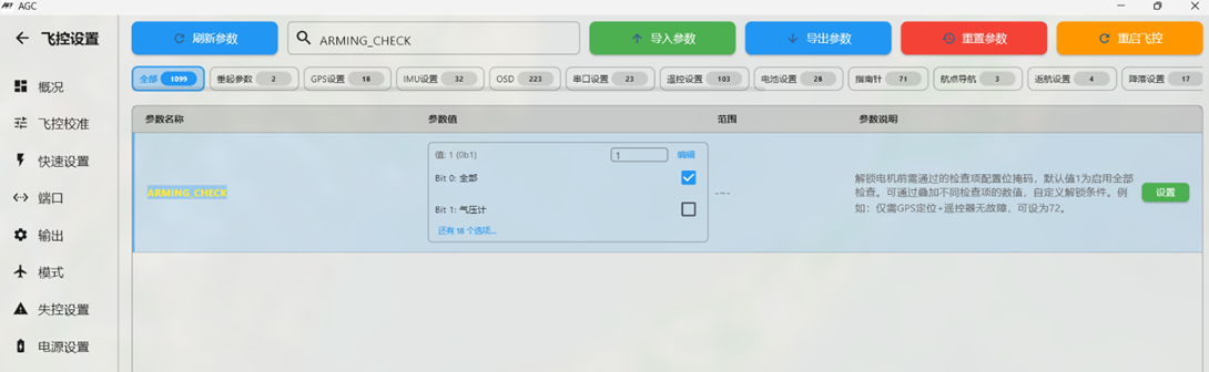 If only specific critical functions require pre-arm checking, select the applicable checks according to the actual aircraft configuration.
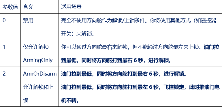
ARMING_RUDDER defaults to 1; change it to 3.
This arming parameter determines whether and how rudder-stick position can be used to arm or disarm the aircraft.
6.3. Enable VTOL Mode
Q_Enable
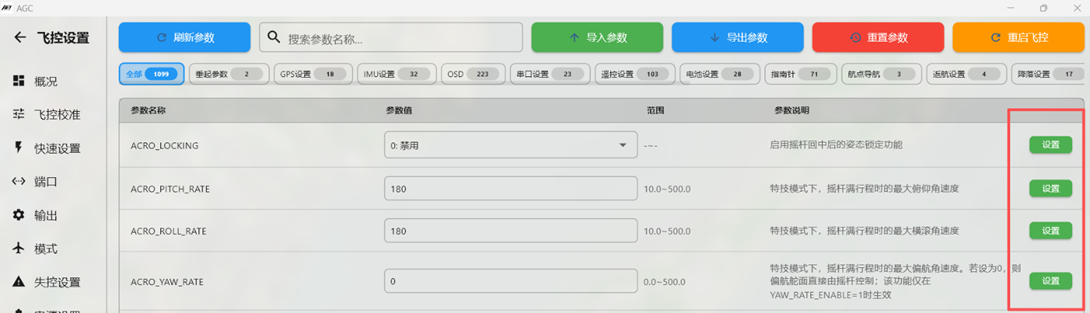
This parameter enables VTOL operation. The default is 0; change it to 1. Click Write Params and click OK when prompted, as shown below. Disconnect power and the USB data cable, restart the flight controller, and reconnect MP.
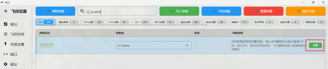
Click Set.
Q_M_Spin_Arm
Motor idle after arming. The default is 0.1; set it to 0 if the motors should remain stopped.
Q_Land_Final_Alt
During multicopter landing, the second landing stage begins at this altitude. The default is 6 meters; change it to 8 meters.
Q_Land_Final_spd
Multicopter descent speed during the second landing stage. The default is 0.5m/s; change it to 0.4m/s.
Q_Trans_Decel
Deceleration rate when transitioning from fixed-wing to multicopter mode. The default is 2m/s; change it to 3m/s.
Q_Transition_MS
Delay before stopping the VTOL motors after transitioning from multicopter to fixed-wing mode. The default is 5000ms; change it to 6000ms (6 seconds).
Q_M_Hover_Learn
The default is 2, enabling automatic throttle learning in multicopter mode.
6.4. Select the Airframe Type
Q_Frame_Class
This parameter selects the VTOL rotor configuration. The default is 1. A 4+1 VTOL uses four lift rotors, corresponding to Quad. Click Write Params. Note: For the Freedom Y3, change the value to 7 (Y configuration).
6.5. VTOL Rotor Frame Type
Q_Frame_Type
Keep the default value of 1. Notes:
VTOL fixed-wing aircraft commonly set this parameter to 1;
A 4+1 VTOL uses a four-rotor X configuration (value 1);
6.6. Tilt Control
Q_Tilt_Enable
For 4+1 aircraft such as the Titan Cobra, or for 4+2 aircraft, tilt control is not required; set the value to 0.
This parameter enables VTOL tilt-vector control. The default is 0 (disabled); change it to 1 for aircraft such as the Freedom Y3 and 4-to-2 tilt configurations. Click Write Params. When prompted to restart, disconnect power and the USB data cable, then reconnect.
Note: For a 4+1 VTOL, set this parameter to 0 (disabled).
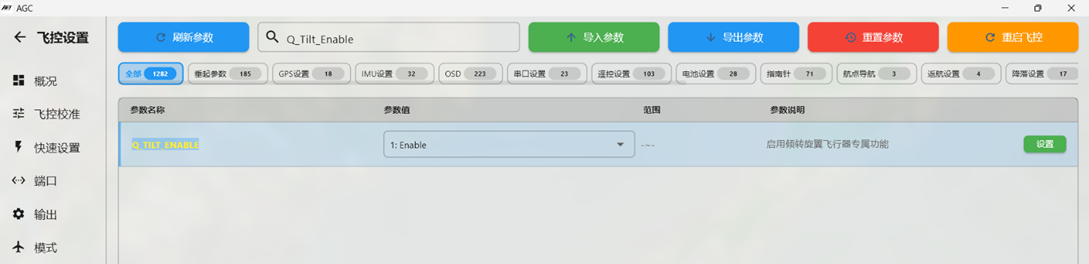
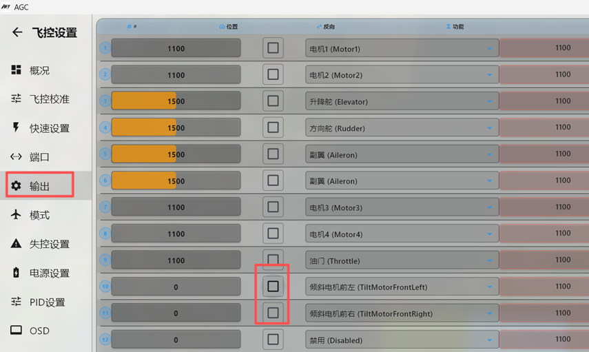
For the subsequent Q_Tilt_xxx parameters, set Q_Tilt_Enable to 1 and reconnect USB for the change to take effect.
Q_Tilt_Type
This parameter selects the VTOL tilt-vector control type. The default is 0; change it to 2 for vectored yaw, which controls aircraft yaw by changing motor thrust direction. Click Write Params.
Q_Tilt_Mask
This parameter identifies the tilt servos used for vector control. Click Set Bitmask on the right, select the Moter1 and Moter3 Servo Output entries, and click Write Params.
Q_Tilt_Yaw_Angle
This parameter sets the rotor YAW-axis control angle. The default is 0; change it to 10 and click Write Params.
Q_Tilt_Fix_Angle
This parameter sets the fixed-wing roll/pitch vector-assist angle. The default is 0; change it to 10 and click Write Params.
Q_Tilt_Fix_Gain
This parameter sets vector-control sensitivity. The default is 0; change it to 0.5 and click Write Params.
Q_Tilt_Rate_DN
This parameter sets the tilt angular rate when transitioning to fixed-wing mode. The default is 0; change it to 25 (25 degrees/second) and click Write Params.
Q_Tilt_Rate_UP
This parameter sets the tilt-servo angular rate when transitioning to multicopter mode. The default is 40; change it to 80 (80 degrees/second) and click Write Params.
Q_Tilt_Max
This parameter sets the initial tilt-servo angle for the transition to fixed-wing mode. The default is 45; change it to 65.
6.7. Loss-of-Control Protection
Q_Assist_Angle
This parameter enables multicopter VTOL assistance when the attitude deviation exceeds the threshold, switching the aircraft to rotor mode. The default is 30; change it to 60 (60 degrees) and click Write Params.
Q_Assist_Speed
This parameter enables multicopter VTOL assistance when speed falls below the configured value. The default is 0; change it to 10m/s to reduce stall risk.
Q_Assist_Alt
This parameter sets the minimum-altitude protection threshold. Below this altitude, multicopter VTOL assistance is enabled. Set it to 20 meters. A fixed-wing-to-VTOL transition typically loses 15-20 meters of altitude.
Q_Angle_Max
Maximum multicopter lean angle for counteracting external forces such as wind. The default is 3000; change it to 4500 (45 degrees).
6.8. Use Tilt Servos for Acceleration or Wind Resistance in Multicopter QLoiter or Loiter Mode
Q_VFWD_Gain
This parameter enables tilt-servo assistance for acceleration or wind resistance in multicopter Loiter mode. The default is 0; change it to 0.05 and click Write Params.
6.9. Prevent Fixed-Wing Transition Below the Minimum Altitude Q_VFWD_Alt
The tilt motors provide forward thrust only above this altitude, preventing the propellers from striking the ground. The default is 0; change it to 2 and click Write Params.
6.10. Set the Default Rotor Mode at Power-On
Initial_Mode
This parameter selects the default flight mode at power-on. The default is 0; change it to 17 (multicopter stabilization mode QStabilize) and click Write Params.
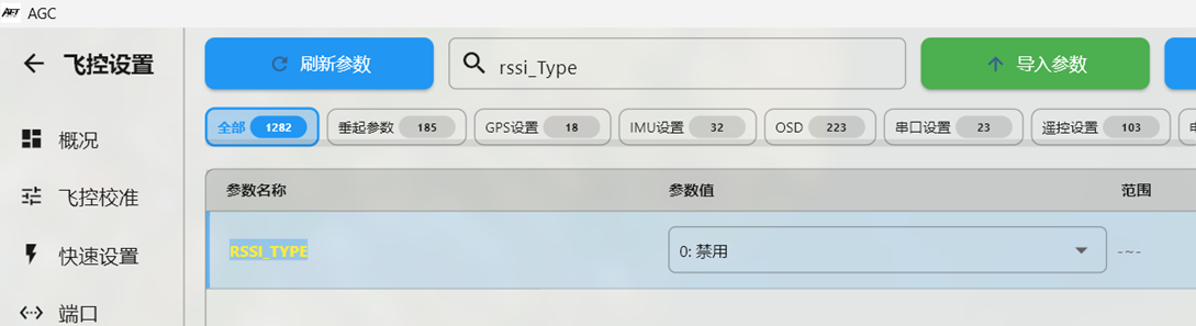
RSSI signal-strength parameter received by the flight controller
Set rssi_Type to 2
P, I, and D Parameters
The following instructions use Mode 2 stick assignments and apply to Y3 aircraft.
Yaw-axis P, I, and D values (radio transmitter left stick, left/right)
Q_A_Rat_YAW_P Default 0.18; change to 0.2
Q_A_Rat_YAW_I Default 0.018
Q_A_Rat_YAW_D Default 0; change to 0.02
Pitch-axis P, I, and D values (radio transmitter right stick, up/down)
Q_A_Rat_PIT_P Default 0.25; change to 0.1
Q_A_Rat_PIT_I Default 0.25
Q_A_Rat_PIT_D Default 0.0036; change to 0.004
Roll-axis P, I, and D values (Mode 2 radio transmitter right stick, left/right)
Q_A_Rat_RLL_P Default 0.25; change to 0.1
Q_A_Rat_RLL_I Default 0.25
Q_A_Rat_RLL_D Default 0.0036; change to 0.004
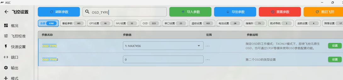
OSD_TYPE
This parameter selects the OSD display mode for the video system.
For a conventional analog 5.8G video transmitter, keep the default value of 1.
For digital video systems using MSP_Displayport, including air units compatible with DJI G2/G3/N3 goggles, Caddx Avatar air units, and OpenIPC open-source digital HD air units, set this parameter to 5.
For older DJI HD V1/V2 goggles with Vista or the original dual-antenna air unit, set this parameter to 3.
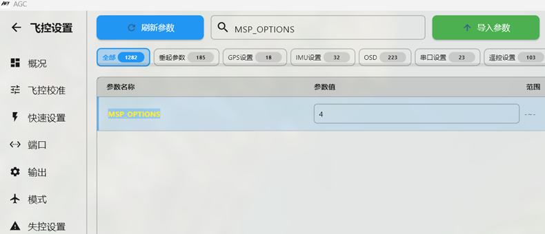
MSP_OPTIONS 4
This parameter must be configured when using an air unit compatible with DJI G2/G3/N3 goggles.
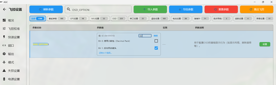
OSD_OPTION 32
This parameter must be configured when using an air unit compatible with DJI G2/G3/N3 goggles.。
For an Openipc open-source digital air unit, set this parameter to 42.
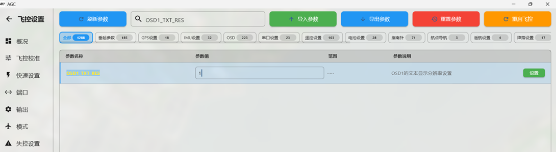
OSD1_TXT_RES 1
This parameter adjusts the OSD resolution and layout. It is recommended for all HD video systems.
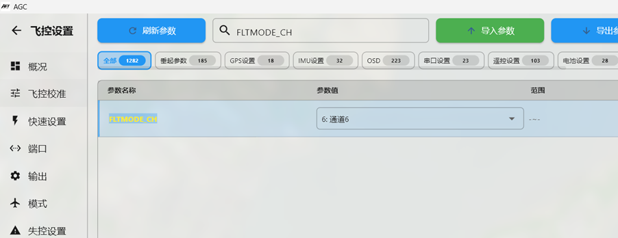
Flight-Mode Selection Channel FLTMODE_CH By default, firmware uses channel 8 for flight-mode selection. Configure radio channel 8 as a six-position switch. With an ELRS receiver, use ELRS3.X or later firmware in 100hzFull or 333HzFull mode. FLTMODE_CH can remain at the default value of 8. To use another channel for the six-position flight-mode switch, such as channel 12, open Full Parameters in Mission Planner and set FLTMODE_CH to 12. For the SIYI MK15 radio transmitter, use the SA three-position switch for flight-mode selection (channel 6, right shoulder switch). In Mission Planner Full Parameters, set FLTMODE_CH to 6.
Maximum Allowed Attitude Angles in FBWA Mode
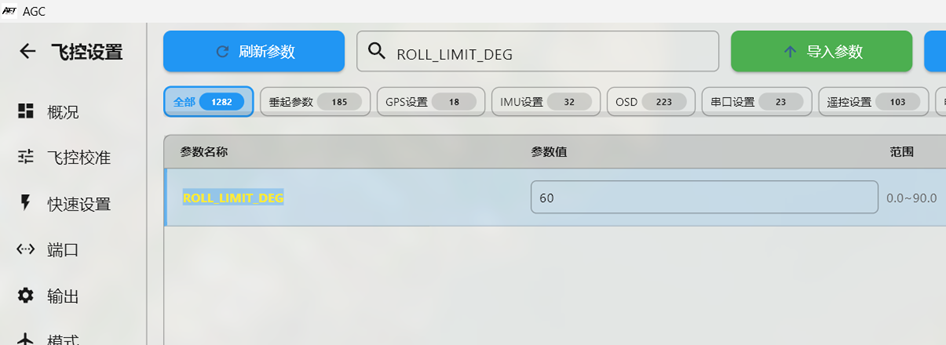
ROLL_LIMIT_DEG 60 Maximum roll angle in FBWA mode. The default is 45. Change it to 60 to reduce the turning radius in FBWA mode.
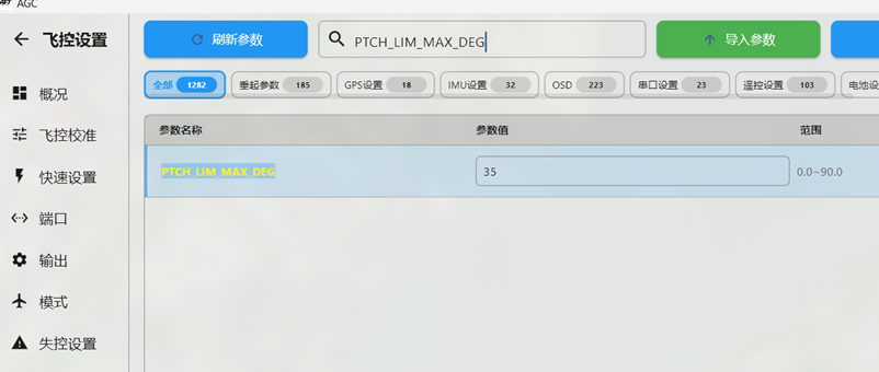
PTCH_LIM_MAX_DEG 35 Maximum pitch angle in FBWA mode
The default is 20. Change it to 35 to allow a steeper climb angle and increase climb rate in FBWA mode.
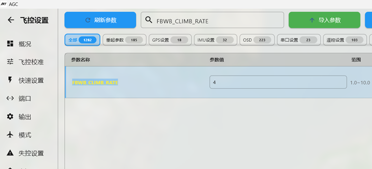
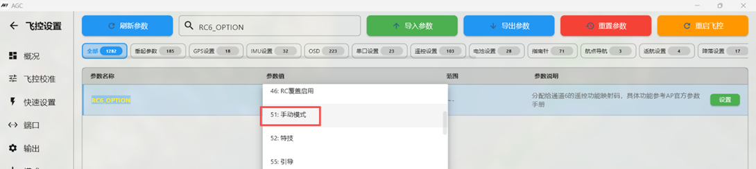
FBWB_CLIMB_RATE 4 (510m/s may be used). CRUISE altitude-and-heading hold is commonly used for long-range flight. The default climb rate is only 2M/s. Adjust this parameter according to the aircraft power system. In CRUISE mode, a pitch-up command from the radio transmitter makes the aircraft climb at the configured rate. Recommended value: 510m/s. The parameter is shown below.
Permitted Control-Surface Travel for Mixed-Control Airframes
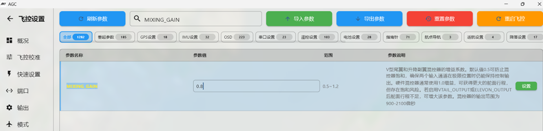
For flying-wing aircraft using elevon mixing and V-tail aircraft using elevator/rudder mixing, the default control-surface travel may be limited. Increase the MIXING_GAIN parameter to increase control-surface movement. The default is 0.5; adjust it to 0.8 or 1 as required.
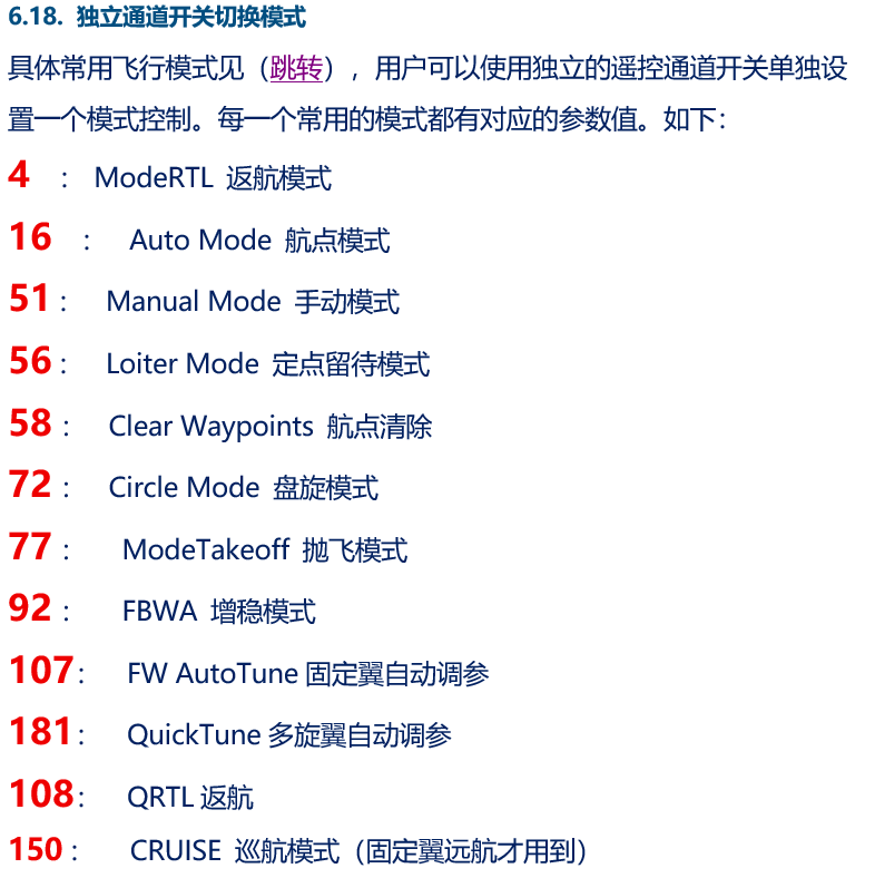

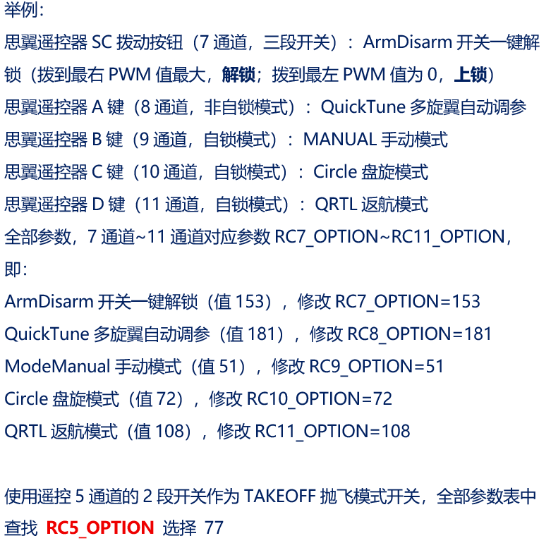
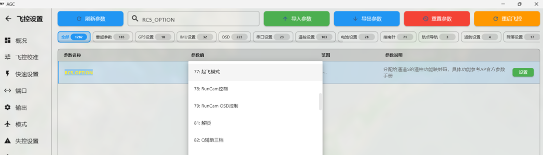

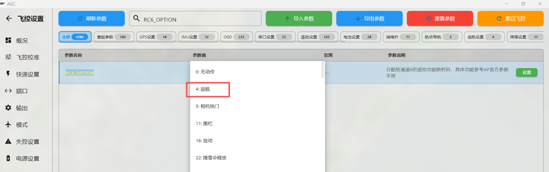

Fixed-Wing AutoTune
AUTOTUNE_LEVEL AutoTune level; keep the default value of 6
AUTOTUNE_AXES AutoTune axes; normally select Roll and Pitch
VTOL AutoTune
Q_AUTOTUNE_AGGR AutoTune aggressiveness; default 0.1, change to 0.09
Q_AUTOTUNE_AXES AutoTune axis. Available axes are Roll, Pitch, and Yaw. Tune only one axis at a time.
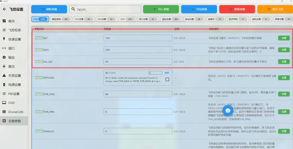
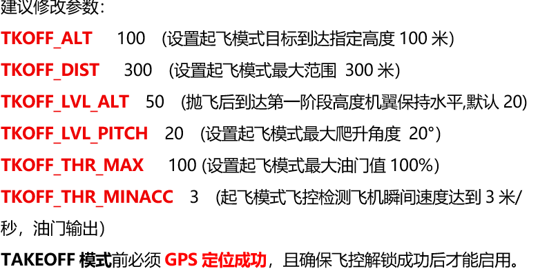
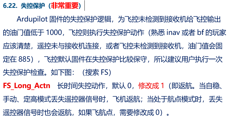
TAKEOFF Hand-Launch Mode Parameters
TAKEOFF hand-launch mode is useful for FPV aircraft launched by hand. After assigning the corresponding flight-mode switch, adjust the applicable hand-launch parameters as required.

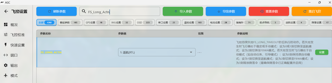
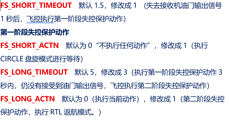
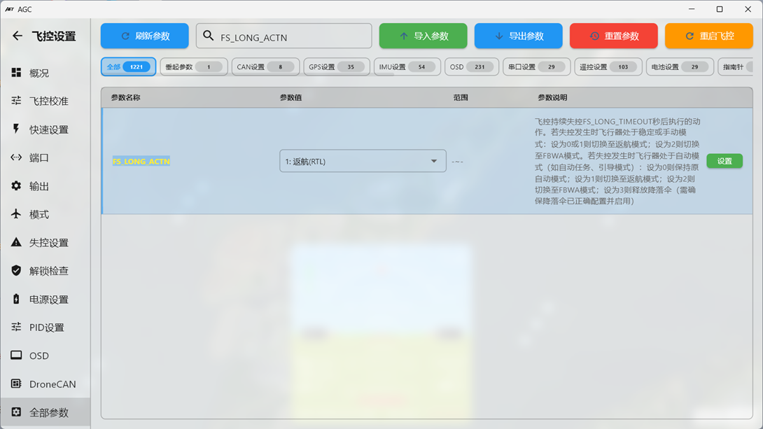
Full Parameters or Fail-Safe Settings
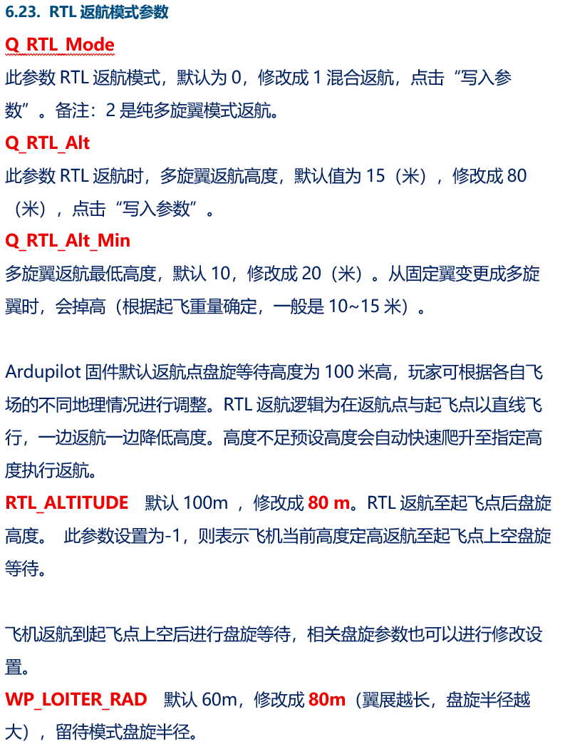
Changing Flight Controller Mounting Orientation with AHRS_ORIENTATION
Some airframes do not provide enough space for the default horizontal flight-controller installation. This is common when converting scale aircraft to FPV, where the controller may need to be mounted on the side of the fuselage or upside down. Set AHRS_ORIENTATION to match the actual flight-controller mounting orientation.
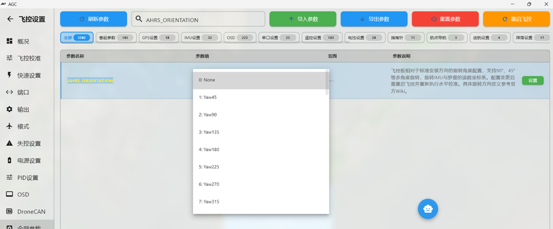
Example 1: If the flight controller main power-lead direction, which normally points toward the nose, points aft, the controller is installed front-to-back. Set the parameter to 4 (YAW 180).
Example 2: If the bottom of the flight controller is mounted against the fuselage side, equivalent to a 90-degree or 270-degree rotation about the ROLL axis, set the parameter to 16 or 20.
Example 3: On the Swordfish airframe, the flight controller must be installed upside down with its normal nose direction pointing aft. This corresponds to ROLL180 plus YAW180. Because no direct option is provided, PITCH 180 produces the required orientation. Set the parameter to 12.