Flight Controller Wiring
2.1. AeroEgg AET H743 Basic Flight Controller Wiring Diagram
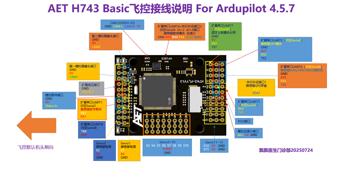 Note the forward orientation of the flight controller. During accelerometer calibration in ArduPilot firmware, the aircraft must be positioned on its left side, right side, and in the other requested orientations.
2.2. Common Peripheral Examples Common peripherals include GPS positioning modules; SBUS, ELRS, and TBS CRSF receivers; digital video air units (including DJI O3, O4, and O4Pro; the Caddx Avatar series; open-source OpenIPC HD video systems; SIYI air units; and Viewpro air units); digital airspeed sensors; and optical-flow rangefinders.
GPS modules, SBUS receivers, ELRS receivers, TBS CRSF receivers, telemetry-link modules, and digital video air units are serial peripherals. The compass in a GPS module and a digital airspeed sensor are I2C bus peripherals.
An I2C airspeed-sensor device can be connected to the flight controller’s SDA2 and SCL2 pins (the connector pinout may need to be modified manually; see Chapter 4, Section 12). Connections used in this example: UART1: digital video air unit (SIYI UART port, 115200, MavLink2).
UART2: GPS module (uart2 and I2C interface, 38400, GPS).
UART4: AeroEgg advanced airspeed sensor (I2C interface; no baud rate or protocol is required).
UART6: ELRS receiver (SIYI s.bus, 115200, RCIN).
UART7: onboard Bluetooth telemetry-link module (115200, MavLink2).
UART8: optical-flow range sensor (115200, MavLink1).
2.3. Serial-Bus Receiver Connection Example
Connect the receiver to UART6 as shown below:
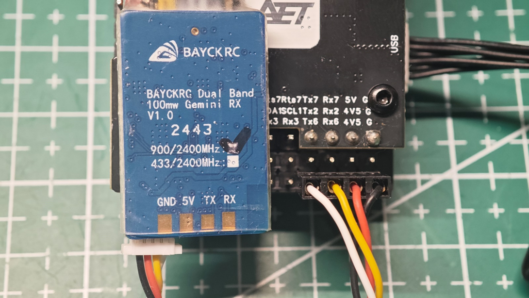
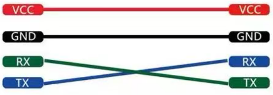
For an ELRS receiver or TBS CRSF receiver, connection to the H743 flight controller’s UART6 port is recommended, as shown above. Follow the pin labels rather than the wire colors. Connect receiver R (or RX) to flight controller Tx6.
Connect receiver T (or TX) to flight controller Rx6.
Connect receiver V (or 5V) to flight controller 4V5.
Connect receiver G (or GND) to flight controller G.
After connecting the device, configure the corresponding port in the ground station.
1.1. GPS Module (Including Electronic Compass) Connection Example
Connect it to the flight controller Uart2 port as shown below:
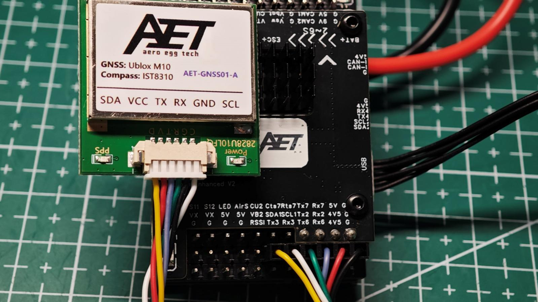
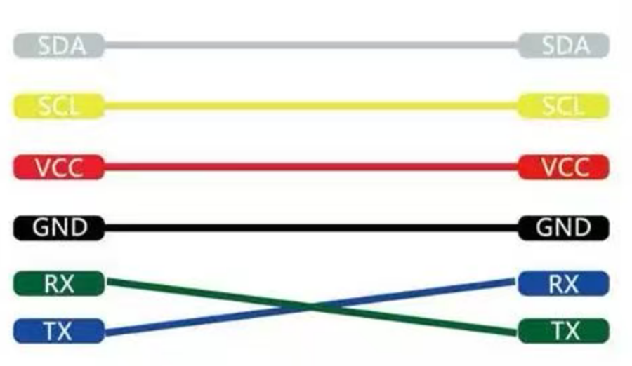
For a GPS module, connection to the flight controller’s UART2 port is recommended, as shown above.
Connect GPS R (or RX) to flight controller TX2, and GPS T (or TX) to flight controller RX2.
Connect GPS V (or 5V) to flight controller 4V5, and GPS G (or GND) to flight controller G.
Connect GPS SCL to flight controller SCL1 and GPS SDA to flight controller SDA1. CL and DA are the I2C bus connections for the electronic compass integrated into the GPS module. A compass is optional on a conventional fixed-wing aircraft. If the GPS module does not include a compass, CL and DA do not need to be connected. After connecting the device, configure the corresponding port in the ground station.。
1.1. Digital Video Air Unit Connection Example
Connect it to the Uart1 port as shown below:
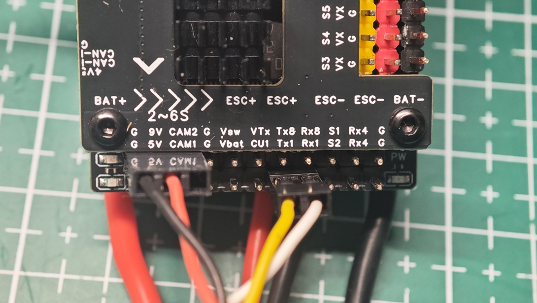
For a DJI digital video air unit, connection to the flight controller’s TX1, RX1, 9V, and GND pins (UART1 port) is recommended.
For a DJI digital video air unit, connection to the flight controller’s TX1, RX1, 9V, and GND pins (UART1 port) is recommended. Connect air-unit R (or RX) to flight controller Tx1, and air-unit T (or TX) to flight controller Rx1.
Connect air-unit V to flight controller 9V, and air-unit G (or GND) to flight controller G.
DJI air units include an SBUS receiver module for pairing with the DJI FPV2 radio transmitter. If the DJI FPV2 radio transmitter is not used, only four wires from the air unit need to be connected to the flight controller.
After connecting the device, configure the corresponding port in the ground station.。
1.3. Servo Connection Example
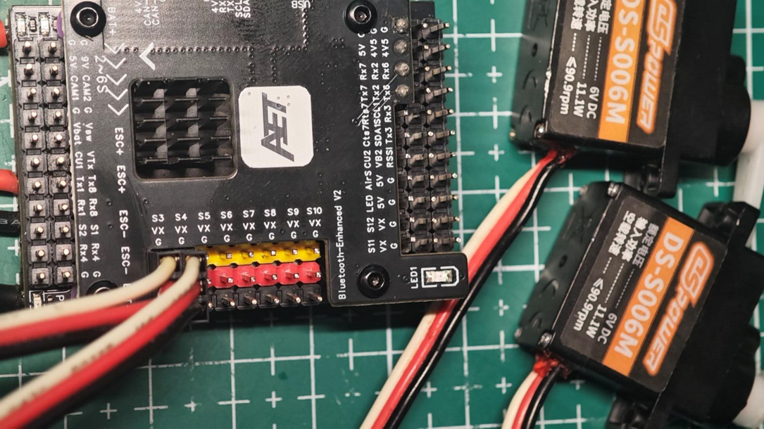
Servo connectors are generally 2.54 mm 3-pin Dupont connectors. The dark wire is normally G (GND), the red or orange-red wire is the positive 5V servo supply, and the white or yellow-orange wire is the servo control signal S. Connect each servo separately to an S3~S12 port on the flight controller; do not combine multiple servo leads into a single connection to the flight controller.
Configure the corresponding custom port settings on the flight controller setup page.
1.4. ESC Signal-Wire Connection Example
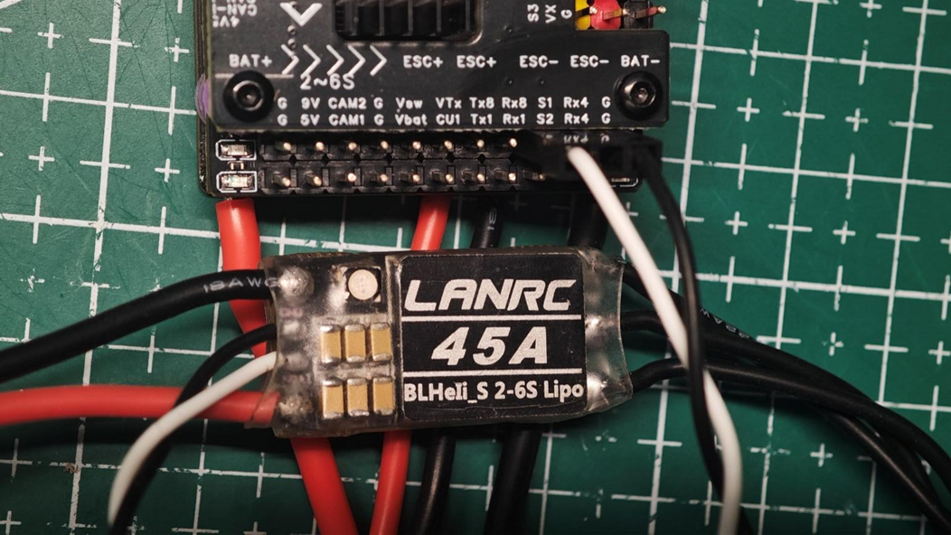 An ESC signal connector is generally a 2.54 mm 3-pin Dupont connector, although the center position is usually unused. The dark or black wire is normally G (GND) and connects to the corresponding S1~S12 port on the flight controller. The light-colored or white wire is the ESC control signal S.
Some ESCs include an integrated BEC 5V output, with a wire from the ESC installed in the center position of the 3-pin Dupont connector.
When the ESC is powered, this center wire outputs 5V and may conflict with the flight controller’s integrated 5V servo-supply BEC. Disconnect or shorten the ESC’s 5V wire before use, and do not connect it to the flight controller.
Configure the corresponding custom settings under AGC Ports on the flight controller setup page.