Servo and ESC Configuration
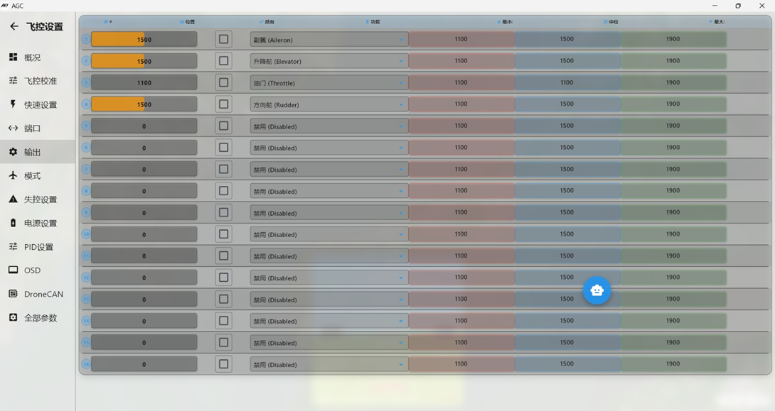 Ardupilot firmware allows the flight controller S1~S12 outputs to be fully customized. In the figure above, #1 corresponds to flight controller output S1, #2 corresponds to S2, and so on.
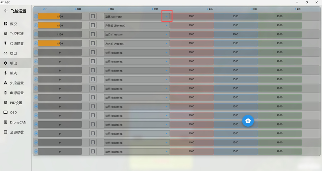 Each output channel can be assigned from its corresponding drop-down menu. This is one of the key capabilities of Ardupilot firmware.
After changing a custom output assignment, restart the flight controller for the setting to take effect.
2.4.1. DSHot ESCs (AM32) DSHot ESCs are available with or without EBC output and support Dshot300, Dshot600, and PWM. The DSHot ESC signal cable normally uses s, v, and g. Connect v only when EBC output is required; otherwise, connect only s and g. Configure the following in the “Full Parameter List”:
1. Set SERVO_BLH_AUTO to 1;
2. Use SERVO_BLH_MASK to specify which output channels, such as throttle channels, use the Dshot protocol. Click Bitmask to select the channels; this example selects “Channel 1.” Note the four Timer groups: channels 12, 36, 7-10, and 11~12. For example, selecting channel 6 enables Dshot on channels 3, 4, 5, and 6 in the same Timer group.
3. Set SERVO_BLH_OTYPE to 5 (Dshot300).
4. Set SERVO_DSHOT_ESC to 1 (BLHeLi32/kiss/AM32). Consult the AM32 ESC supplier before applying this setting.
5. In Mission Planner, open the “Messages” tab on the “Flight Data” page. The output should show DS300:1-2 and PWM:3-12. DS300:1-2 means channels 1~2 use the DS300 protocol.
2.4.2. Reversing Outputs
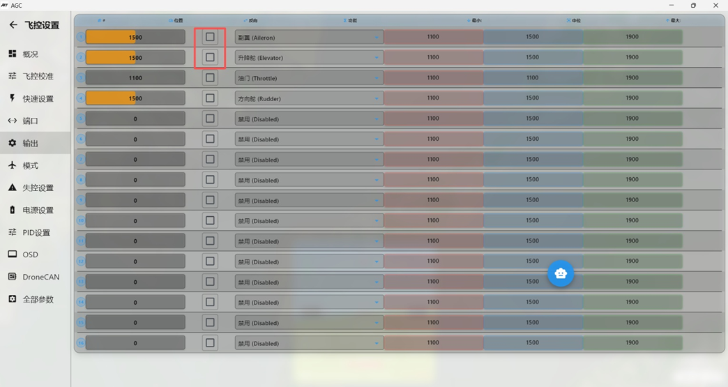
AGC displays channel outputs in real time. During later auxiliary channel correction, if a channel moves in the wrong direction when the flight controller applies an attitude correction, enable “Reverse” for that channel to reverse its output.
2.4.3. Example 1: Single Rear Pusher
Example 1: For a single-engine rear-pusher flying wing such as ARWING or Freedom, connect the left elevon servo to S3. If the servo moves in the wrong direction during setup, enable Reverse for #3. Connect the ESC throttle signal wire to S1.
2.4.4. Example 2: Twin-Engine Vertical-Tail Aircraft with Differential Thrust
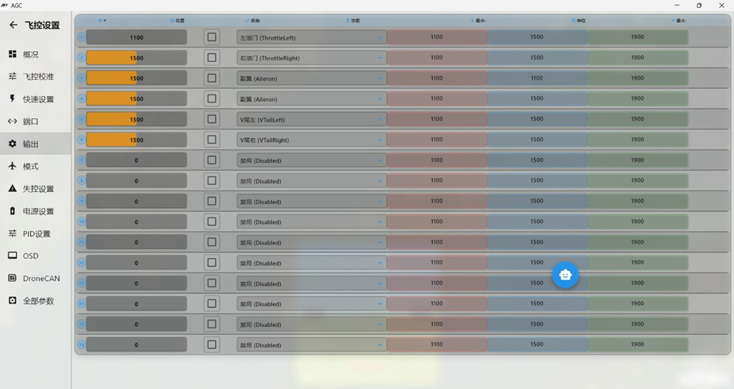
2: Use differential thrust control for the two motors.
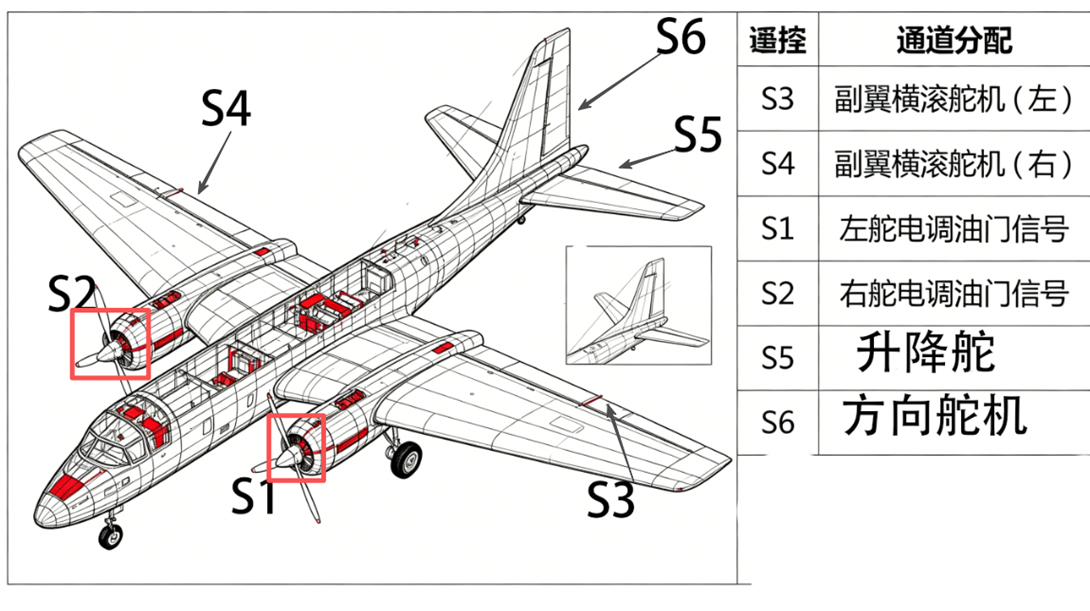
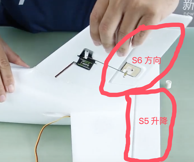
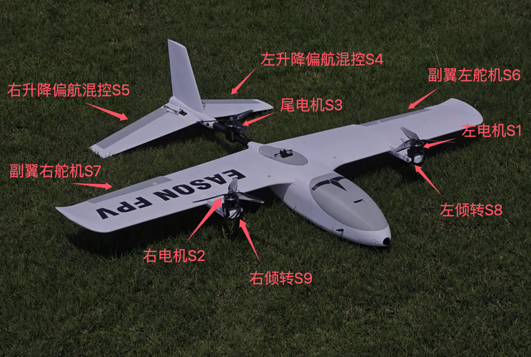
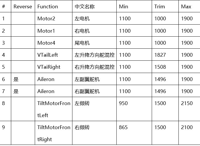
2.4.5. Example 4: Freedom Y3 or Hornet Y3 VTOL Fixed-Wing Aircraft Example 4: A Freedom Y3 VTOL fixed-wing aircraft uses three motor rotors during vertical takeoff and landing. In cruise flight, the two front motors tilt forward and the tail motor stops.
2.4.6. Example 5: 4+1 Titan Cobra or Avenger
The Titan Cobra, Titan Avenger, and Jingyi Dahongweng are all 4+1 VTOL fixed-wing aircraft.
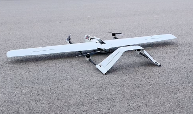
Titan Cobra shown above.
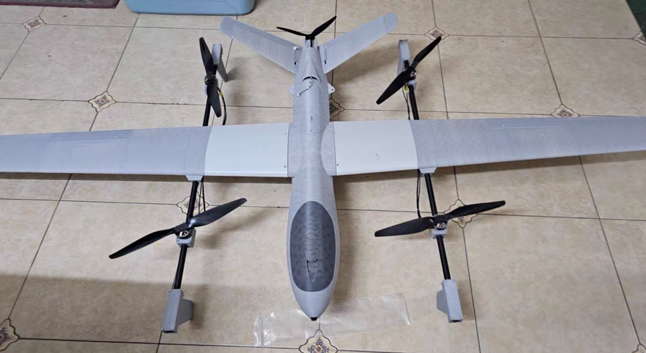 Titan Avenger shown above.
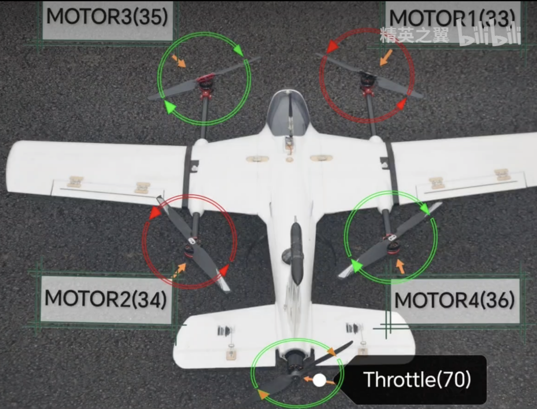 Jingyi Dahongweng
The following Titan Avenger example shows the channel assignments. Configure Servo in the flight controller before powering the servos; otherwise, the servos can be damaged.
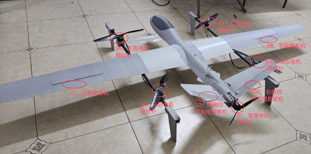 Important: If the rear pusher motor uses an AM32 ESC, observe the Timer group assignments. In this example, Servo channel 1 uses the DSHot protocol. Because of Timer grouping, channel 2 also uses DSHot; all other channels use PWM by default.
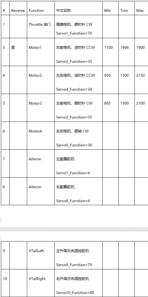
2.4.7. Example 6: Converting a Four-Motor Albatross to a Two-Tilt-Motor VTOL
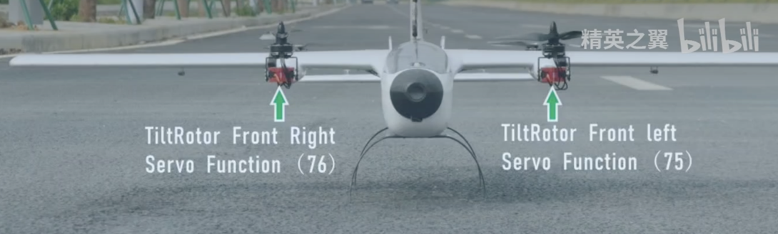
The Albatross is a conventional twin-engine fixed-wing aircraft with vertical tails. After conversion to VTOL, it uses four motors. The two front motors tilt through servos, and there is no rear pusher motor. Servo1: Left aileron
Servo2: Right aileron
Servo3: Left elevon servo
Servo4: Right elevon servo
Servo5: Front-right ESC, reversed rotation
Servo6: Rear-left ESC, reversed rotation
Servo7: Front-left ESC, normal rotation
Servo8: Rear-right ESC, normal rotation
Set Servo9_Function to 75 (front-left tilt servo, TiltMotorFrontLeft, viewed from the tail toward the nose).
Set Servo10_Function to 76 (front-right tilt servo, TiltMotorFrontRight, viewed from the tail toward the nose).
Adjust the tilt angle using Servo9_Min, Servo9_Max, Servo10_Min, and Servo10_Max.
2.4.8. Example 4: Servo-Controlled Gimbal
Example 4: To connect a servo gimbal to flight controller output S8 and control the FPV camera viewing direction with radio transmitter channel 10 assigned to a custom knob, set #8 to RCIN10.
2.5. Section 5: Ports
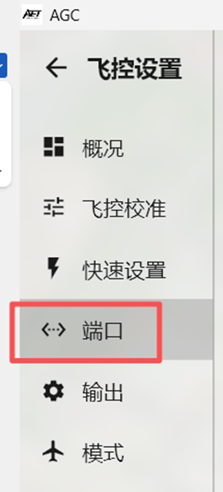
Define each peripheral connected to a flight controller serial-bus interface.
The first column, Port Name, identifies the serial port. For example, SERIAL PORT2 means serial port 2, or UART2. The Speed column sets the baud rate for the interface.
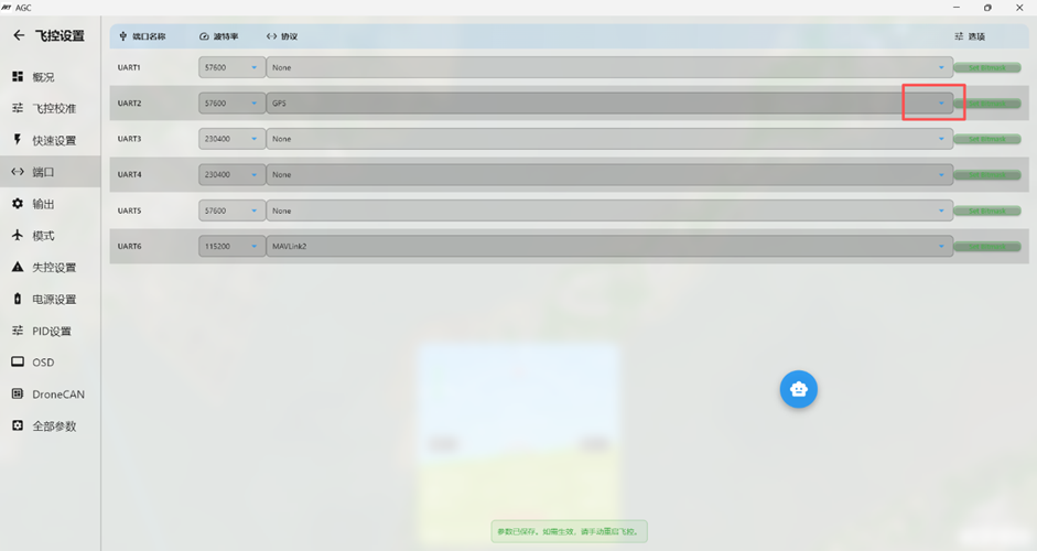
The Protcol column defines the interface type. Set the Speed and Protcol values according to the connected serial peripheral.
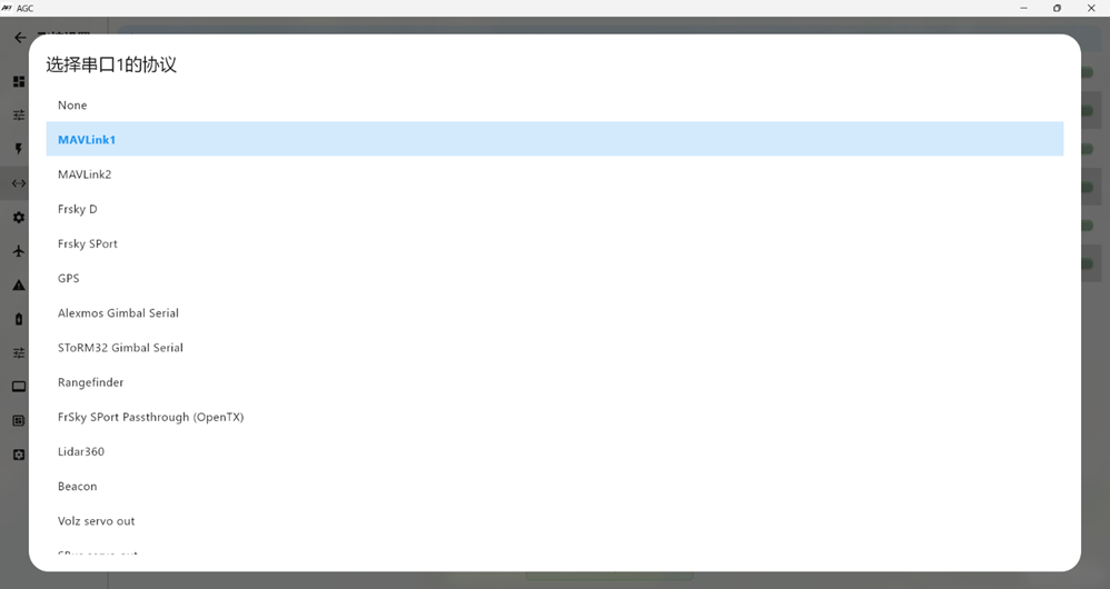
2.5.1. Receiver Configuration
For an SBUS receiver, such as a Tiandifei wbus, RadioLink series, or Futaba series receiver, use a 2.54 mm 3-pin DuPont connector and connect it to RX6-4V5-GND on flight controller SERIAL PORT6 (UART6). Set the baud rate to 57600 and the protocol to RCIN; the SBUS signal is then detected automatically.
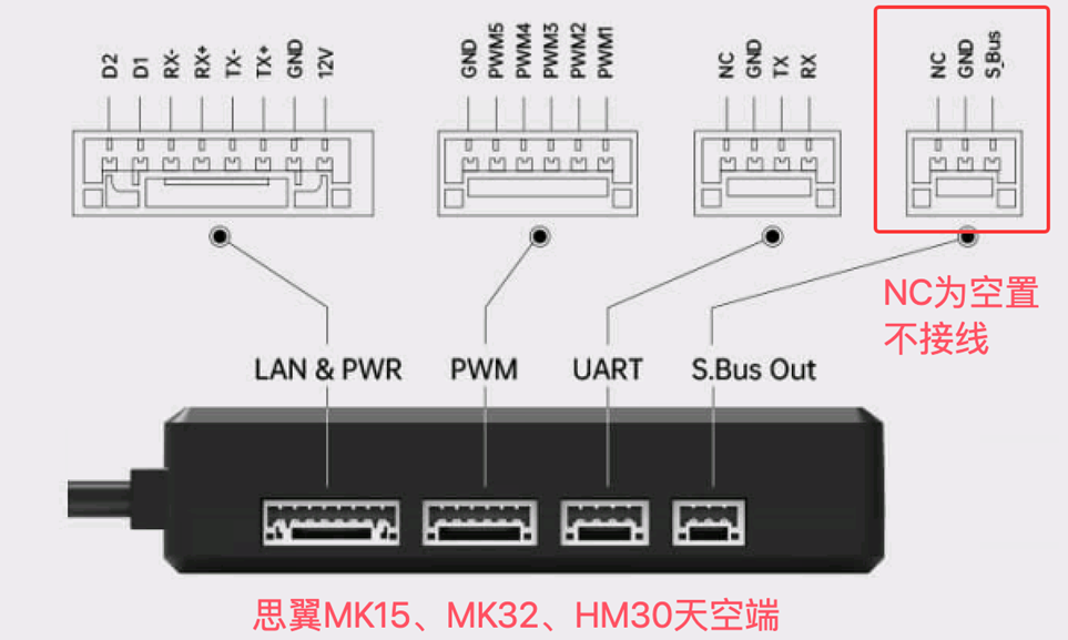
For a SIYI integrated video, telemetry, and radio-control module, use a GH1.25-3Pin to 2.54 mm DuPont 3-pin signal cable. Connect the flight controller end to RX6-GND on SERIAL PORT6 (UART6), and connect the SIYI air-unit end to S.Bus Out. Cut or isolate the NC wire and do not connect it to the flight controller. In MP, set the baud rate to 115200 and the protocol to RCIN. On the SIYI MK15 radio transmitter, open the SIYI app telemetry settings, set the serial baud rate to 115200, set the flight controller to Custom, and select UDP or serial connection.
 For an ELRS/CRSF receiver, use a 2.54 mm DuPont 4-pin connector.
Connect it to TX6-RX6-4V5-GND on flight controller SERIAL PORT6 (UART6).
For this receiver type, set Speed to 115200 and the protocol to RCIN.
Note: The flight controller firmware no longer supports PPM or PWM signal receivers.
2.5.2. GPS Module Configuration
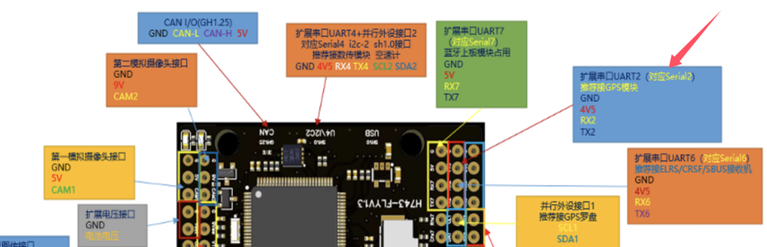
Use a 2.54 mm DuPont 4-pin or 6-pin connector for the GPS module; the 6-pin version includes the compass. Connect it to flight controller SERIAL PORT2 (UART2) in the order SDA1-SCL1-TX2-RX2-4V5-GND. Most GPS modules use 38400 and GPS. Some GPS modules support a Speed value up to 115200. A GPS without a compass uses only TX, RX, 5V, and GND.
For an ELRS/CRSF receiver, use a 2.54 mm DuPont 4-pin connector.
Connect it to TX6-RX6-4V5-GND on flight controller SERIAL PORT6 (UART6).
For this receiver type, set Speed to 115200 and the protocol to RCIN.
Note: The flight controller firmware no longer supports PPM or PWM signal receivers.
2.5.2. GPS Module Configuration
Use a 2.54 mm DuPont 4-pin or 6-pin connector for the GPS module; the 6-pin version includes the compass. Connect it to flight controller SERIAL PORT2 (UART2) in the order SDA1-SCL1-TX2-RX2-4V5-GND. Most GPS modules use 38400 and GPS. Some GPS modules support a Speed value up to 115200. A GPS without a compass uses only TX, RX, 5V, and GND.
 2.5.3. Digital Video Air-Unit Configuration
Connect the digital video air unit to flight controller SERIAL PORT1 (UART1) using a 2.54 mm DuPont 4-pin connector in the order TX1 RX1 9V GND.
Digital video air units normally use 115200 and DispiayPort. Supported examples include DJI O3 and O4 video transmitters with DJI G2, G3, or N3 goggles, noting that N3 goggles support only O4; Caddx Avatar air units; OpenIPC open-source HD video systems such as RunCam WiFiLink2; SIYI air units such as MK15, MK32, and HM30; and Yunzhuo air units.
For DJI V1 or V2 goggles with older DJI air units or Vista, set the UART1 Protcol value to DJI FPV.
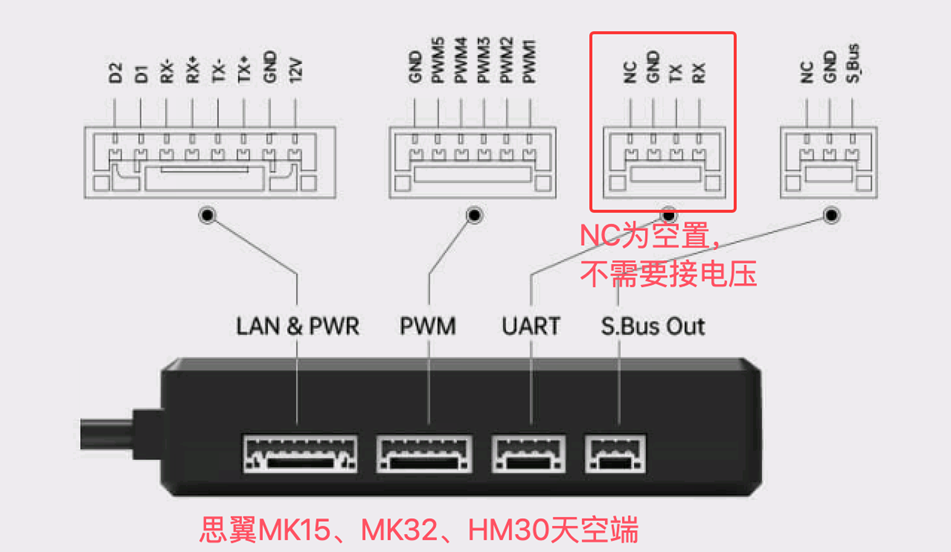
For a SIYI integrated telemetry and radio-control module, use 115200 and Mavlink2. Connect the module to the flight controller with a GH1.25-4Pin to DuPont 4-pin signal cable. Leave NC unconnected; no voltage connection is required. The wire order is NC, GND, RX1, TX1.
2.5.3. Digital Video Air-Unit Configuration
Connect the digital video air unit to flight controller SERIAL PORT1 (UART1) using a 2.54 mm DuPont 4-pin connector in the order TX1 RX1 9V GND.
Digital video air units normally use 115200 and DispiayPort. Supported examples include DJI O3 and O4 video transmitters with DJI G2, G3, or N3 goggles, noting that N3 goggles support only O4; Caddx Avatar air units; OpenIPC open-source HD video systems such as RunCam WiFiLink2; SIYI air units such as MK15, MK32, and HM30; and Yunzhuo air units.
For DJI V1 or V2 goggles with older DJI air units or Vista, set the UART1 Protcol value to DJI FPV.
For a SIYI integrated telemetry and radio-control module, use 115200 and Mavlink2. Connect the module to the flight controller with a GH1.25-4Pin to DuPont 4-pin signal cable. Leave NC unconnected; no voltage connection is required. The wire order is NC, GND, RX1, TX1.
 2.5.4. Onboard Bluetooth Telemetry Module Configuration
The onboard Bluetooth telemetry module on the AET H743 Basic flight controller is assigned directly to SERIAL PORT7 (UART7). Set this interface to 115200 and Mavlink2.
2.5.5. Other Telemetry Module Configuration
Connect an external telemetry module to TX3 and RX3 on the flight controller, corresponding to UART3. Typical telemetry settings are 115200 and Mavlink2.
2.5.6. Optical-Flow Range Sensor Configuration
Use an SH1.0-4P to 2.54 mm DuPont 4-pin cable to connect the sensor to TX8-RX8-4V5-GND on the flight controller, corresponding to UART8. Typical settings are 115200 and Mavlink1.
2.5.7. Serial-Port Configuration Example
 UART1: Digital video air unit (SIYI UART port, 115200, MavLink2).
UART2: GPS module (parallel uart2 and i2c interfaces, 38400, GPS).
UART4: AeroEgg advanced airspeed sensor (parallel i2c interface; no baud rate or protocol required).
UART6: ELRS receiver (SIYI s.bus, 115200, RCIN).
UART7: Onboard flight controller Bluetooth telemetry module (115200, MavLink2).
UART8: Optical-flow range sensor (115200, MavLink1).
Prerequisite 2: Remove the propellers before connecting the battery. Keep all objects away from the motors.
Prerequisite 3: Power on the radio transmitter and confirm that it is correctly bound to the receiver. If the receiver wiring to the flight controller or the corresponding serial-port configuration is incorrect, the radio calibration page will not display the Thrttle signal or channel values for channels 5~16, as shown below:
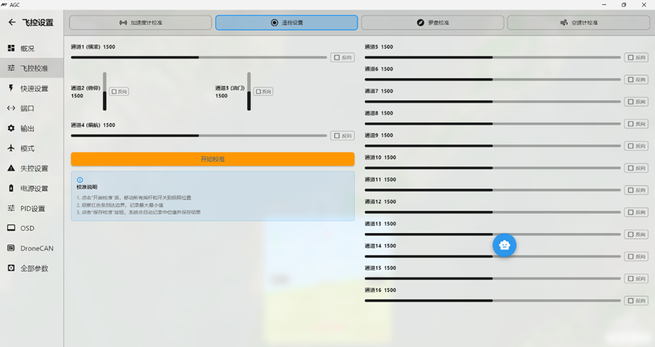 If the receiver is wired correctly to the flight controller and the corresponding serial port is configured correctly, all channels will be visible and will respond to radio transmitter input.
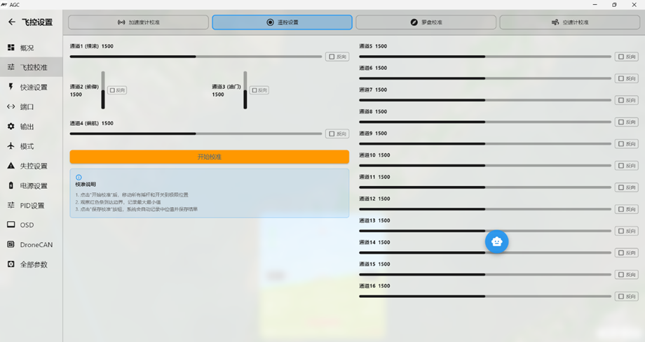 You can now calibrate the radio transmitter sticks and other switch channels.